


 English
 Français
 عربى
عربى
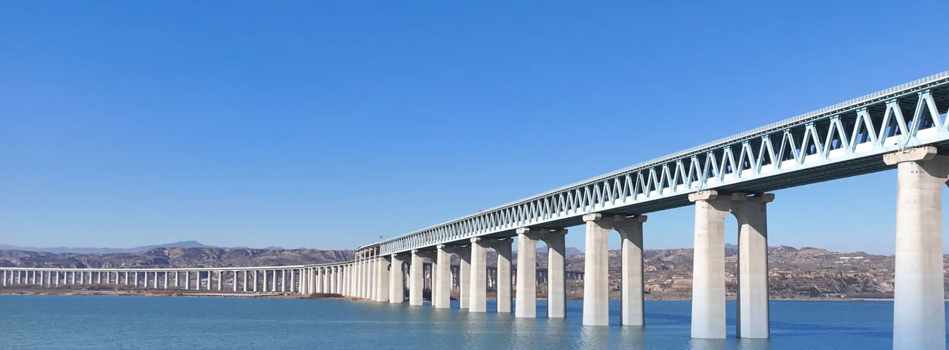
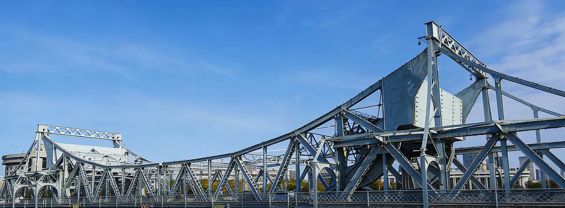
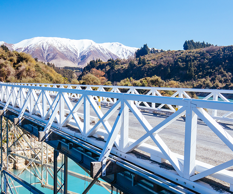
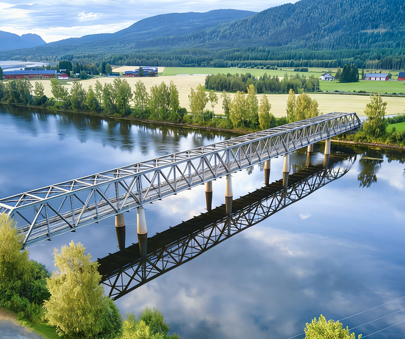
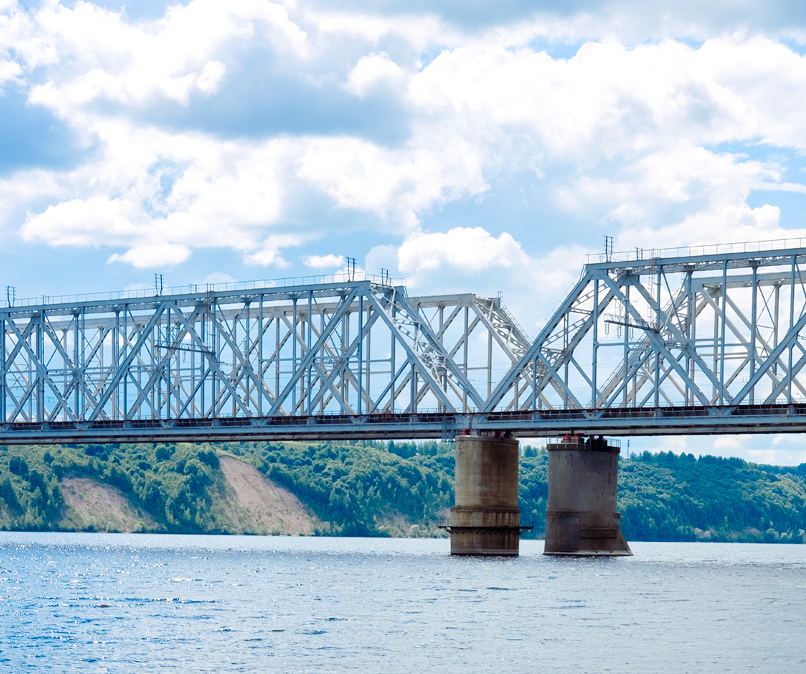
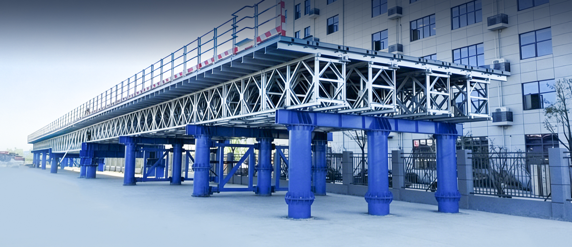
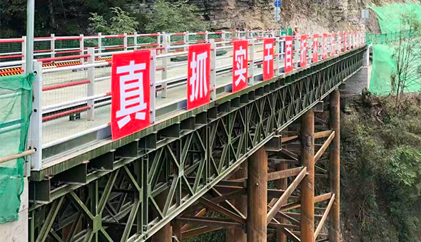
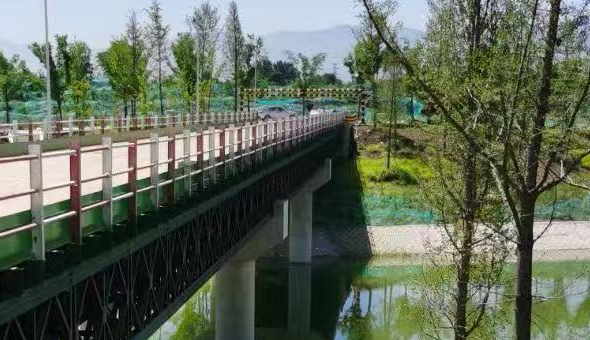
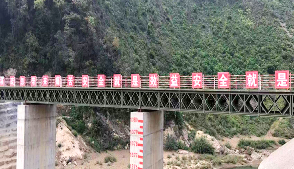
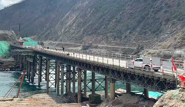
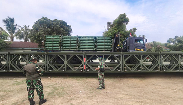
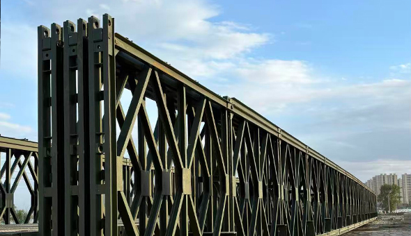
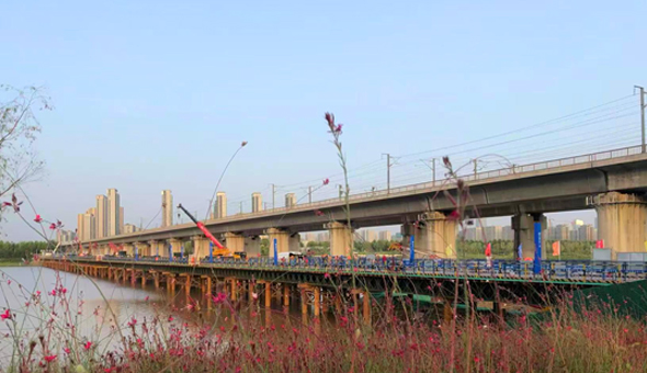
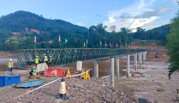
Los puentes de carretera de acero prefabricados son un tipo de puente modular que se puede construir rápidamente y se utilizan principalmente para reparaciones de emergencia. Estos componentes del puente tienen las siguientes características: 1. Están fabricados en acero de alta resistencia y están totalmente soldados. Las vigas principales son generalmente cerchas ligeras desmontables, ensambladas en unidades tridimensionales o planas, conectadas mediante pasadores o pernos individuales. Son livianos, lo que hace que su transporte y desmontaje sean convenientes. 2. Los componentes son intercambiables y pueden reutilizarse varias veces. 3. La combinación de las vigas principales del puente se puede ajustar en función de la longitud y la capacidad de carga. Desde la Segunda Guerra Mundial, varios países importantes han estandarizado y producido sus propios equipos de reparación de puentes. Por ejemplo, el "PMM" de la ex Unión Soviética tenía una viga principal de celosía triangular con soporte superior y unidades de ensamblaje tridimensionales. El puente militar japonés "Tipo 99" también utilizaba una viga principal de celosía triangular con unidades de ensamblaje tridimensionales, principalmente para la reparación de puentes ferroviarios. Este equipo todavía se puede ver en los departamentos ferroviarios de mi país y en algunas unidades de construcción de carreteras, donde a menudo se utiliza como equipo de construcción. Ya al comienzo de la Segunda Guerra Mundial, en 1938, Gran Bretaña y Estados Unidos adoptaron el "puente Bailey", un puente de armadura de acero diseñado por el ingeniero británico Donald Bailey, como puente militar para las fuerzas aliadas. Este puente fue ampliamente utilizado en Europa y el Lejano Oriente durante la Segunda Guerra Mundial, y fue mejorado y desarrollado aún más después de la guerra. Los puentes prefabricados de acero para carreteras de mi país fueron estandarizados y puestos en producción en la década de 1960, originalmente llamados puente de acero para carreteras "321". El Estado dispuso que tres fábricas designadas los produjeran, con una producción anual de aproximadamente 1.500 a 2.000 toneladas, almacenadas en todo el país. Este equipo jugó un papel importante en el socorro en casos de desastre (como el terremoto de Tangshan) y en los contraataques de autodefensa fronteriza. En 1992, durante las operaciones de mantenimiento de la paz en Camboya, las tropas de ingeniería chinas utilizaron componentes de puentes de acero de carretera "321" de producción nacional en la autopista 6, reparando puentes a un ritmo de un puente cada dos días y completando la construcción de seis puentes de carretera en un tramo de carretera de 217 km en 15 días, recibiendo grandes elogios de las fuerzas de mantenimiento de la paz de las Naciones Unidas. El puente de acero para carretera "321" fabricado en mi país es similar al "puente Bailey" británico, y las vigas principales también son cerchas de celosía, pero las dimensiones son diferentes. El puente Bailey utiliza unidades imperiales, mientras que el puente de acero para carreteras "321" utiliza unidades métricas, y estos dos tipos de equipos no se pueden mezclar. Los trabajadores de algunas obras de construcción en mi país a menudo se refieren a las cerchas de acero para puentes de carreteras "321" de producción nacional como "cerchas Bailey" Los componentes del puente Bailey en mi país han sufrido continuas actualizaciones y evolución para adaptarse a las necesidades de más aplicaciones. El puente Bailey tipo HD200, que está surgiendo gradualmente, mejora aún más la resistencia a la flexión y al corte del puente de acero, evolucionando hacia tramos más grandes y cargas más pesadas. En el sector de la vivienda, se puede combinar en una estructura de marco aéreo, que sirve como plataforma de construcción y sube gradualmente hacia arriba mediante la coordinación de estructuras de elevación hidráulicas. Como estructura de soporte fundida in situ, los componentes del puente Bailey se modifican para formar una estructura de soporte superior, complementada con vigas, soportes y otros materiales, que se pueden utilizar para encofrados y vertido de hormigón.
Ver más


Carretera & Puente de Zhenjiang Jinhao
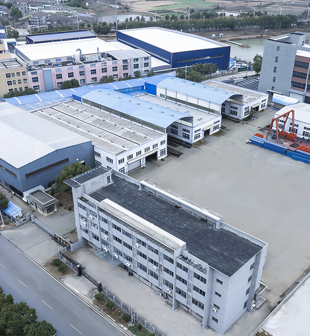
Carretera y puente Jinhao es un fabricante orientado a la ingeniería que se especializa en sistemas de puentes temporales y equipos para la construcción de puentes.
Ofrecemos soluciones integradas que abarcan diseño, fabricación, instalación y alquiler, con núcleo productos que incluyen sistemas de puentes Bailey, viajeros de encofrado y encofrados de acero, que dan servicio a carreteras, Proyectos de infraestructura ferroviaria, municipal y hídrica en todo el mundo.
-
0 m²
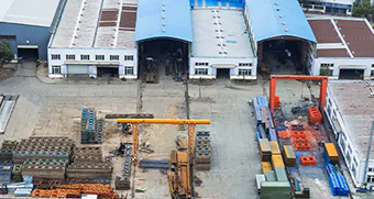
Instalación de producción
Categoría de producto
-
+Puente Bailey
-
+Pórtico de lanzamiento en voladizo
El pórtico de lanzamiento en voladizo es un equipo especializado central para la construcción de puentes de gran envergadura mediante fundición en voladizo, ampliamente utilizado en la construcción de puentes de carreteras y ferrocarriles, especialmente adecuado para escenarios de terrenos complejos como cruces de ríos, valles y líneas existentes. Es un equipo clave para lograr la construcción de puentes en voladizo a gran altitud. Este producto está fabricado principalmente con estructura de acero, adopta un diseño modular y puede avanzar gradualmente con el progreso de la construcción. Combina un posicionamiento preciso y un rendimiento de carga estable, proporcionando una plataforma de trabajo segura y confiable para la fundición de la viga principal del puente. Las principales ventajas del pórtico de lanzamiento en voladizo son extremadamente significativas. Su diseño estructural liviano combina alta resistencia y rigidez, con una baja relación de peso propio, lo que reduce efectivamente la tensión adicional en la viga principal del puente durante la construcción y garantiza la precisión de la fundición. El equipo es altamente adaptable y se puede ajustar de manera flexible de acuerdo con el tamaño de la sección del puente y los requisitos de tramo, eliminando la necesidad de un diseño de sitio de gran área y reduciendo en gran medida la dificultad de construcción en terrenos complejos. Al mismo tiempo, es fácil de operar, tiene buena sincronización de movimiento hacia adelante, alta eficiencia constructiva y está equipado con un completo sistema de protección de seguridad, evitando eficazmente riesgos laborales a gran altitud. En comparación con los equipos de construcción tradicionales, el pórtico de lanzamiento en voladizo tiene un período de construcción más corto y menos interferencia con el entorno circundante, lo que mejora significativamente la calidad del proyecto y la seguridad de la construcción. Durante el uso, es necesario verificar estrictamente la precisión del montaje y el estado de tensión del pórtico de lanzamiento, y comprobar periódicamente la estanqueidad de las piezas de conexión y el desgaste de la estructura; Durante la construcción se deben respetar los límites de carga y está estrictamente prohibido el apilamiento ilegal de materiales, implementando simultáneamente medidas a prueba de viento y antivuelco. Con sus características principales de "eficiencia, precisión y seguridad", el pórtico de lanzamiento en voladizo se ha convertido en el equipo preferido en el campo de la construcción de puentes de gran envergadura, demostrando un gran valor práctico de ingeniería.Ver más -
+Encofrado de acero para puentes
El encofrado de acero para puentes es un equipo de soporte central para la construcción de hormigón de puentes de carreteras y ferrocarriles. Se utiliza ampliamente en la formación de pilares de puentes, estribos, vigas cajón, vigas en T y otros componentes, y es una instalación clave para garantizar la precisión dimensional y la calidad de apariencia de las estructuras de hormigón. Fabricado con acero de alta calidad y procesado mediante corte y soldadura de precisión, este producto presenta una estructura regular, juntas herméticas y una gran capacidad de carga. Puede adaptarse con precisión a las necesidades de construcción de diferentes formas y tamaños de secciones transversales, proporcionando una plataforma de conformado estable y confiable para el vertido de concreto. Las principales ventajas del encofrado de acero para puentes son especialmente destacadas. En comparación con el encofrado de madera tradicional, ofrece resistencia y rigidez superiores, resistiendo eficazmente la presión lateral del hormigón y evitando la deformación y deformación de la construcción, mejorando significativamente la precisión de la formación de componentes. La superficie lisa y plana del encofrado da como resultado una excelente apariencia del hormigón después del desmoldeo, eliminando la necesidad de acabados complejos adicionales y acortando significativamente el ciclo de construcción. También cuenta con una excelente reutilización; con una adecuada eliminación y mantenimiento del óxido, se puede utilizar repetidamente, reduciendo los costos de materiales y minimizando los desechos de construcción, equilibrando así la eficiencia económica y la protección del medio ambiente. Además, su cómodo montaje y buen sellado evitan fugas y reducen el retrabajo, garantizando eficazmente la calidad del proyecto. Durante el uso, se debe verificar estrictamente la precisión del ensamblaje, la planitud y la estanqueidad de la conexión del encofrado de acero del puente para garantizar la coherencia con las dimensiones del diseño; Se debe realizar la eliminación de óxido y la aplicación de agente desmoldante antes del vertido, y se debe monitorear el estado de tensión del encofrado en tiempo real durante el vertido para evitar sobrecargas locales o una distribución desigual de la tensión. Con sus características principales de "precisión, durabilidad y eficiencia", se ha convertido en el equipo preferido para la construcción de puentes de alta calidad, lo que demuestra su valor práctico indispensable en diversos proyectos de construcción de puentes.Ver más

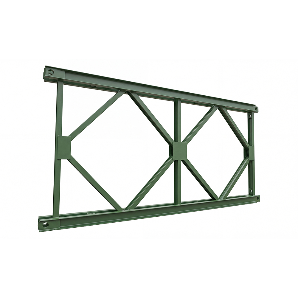
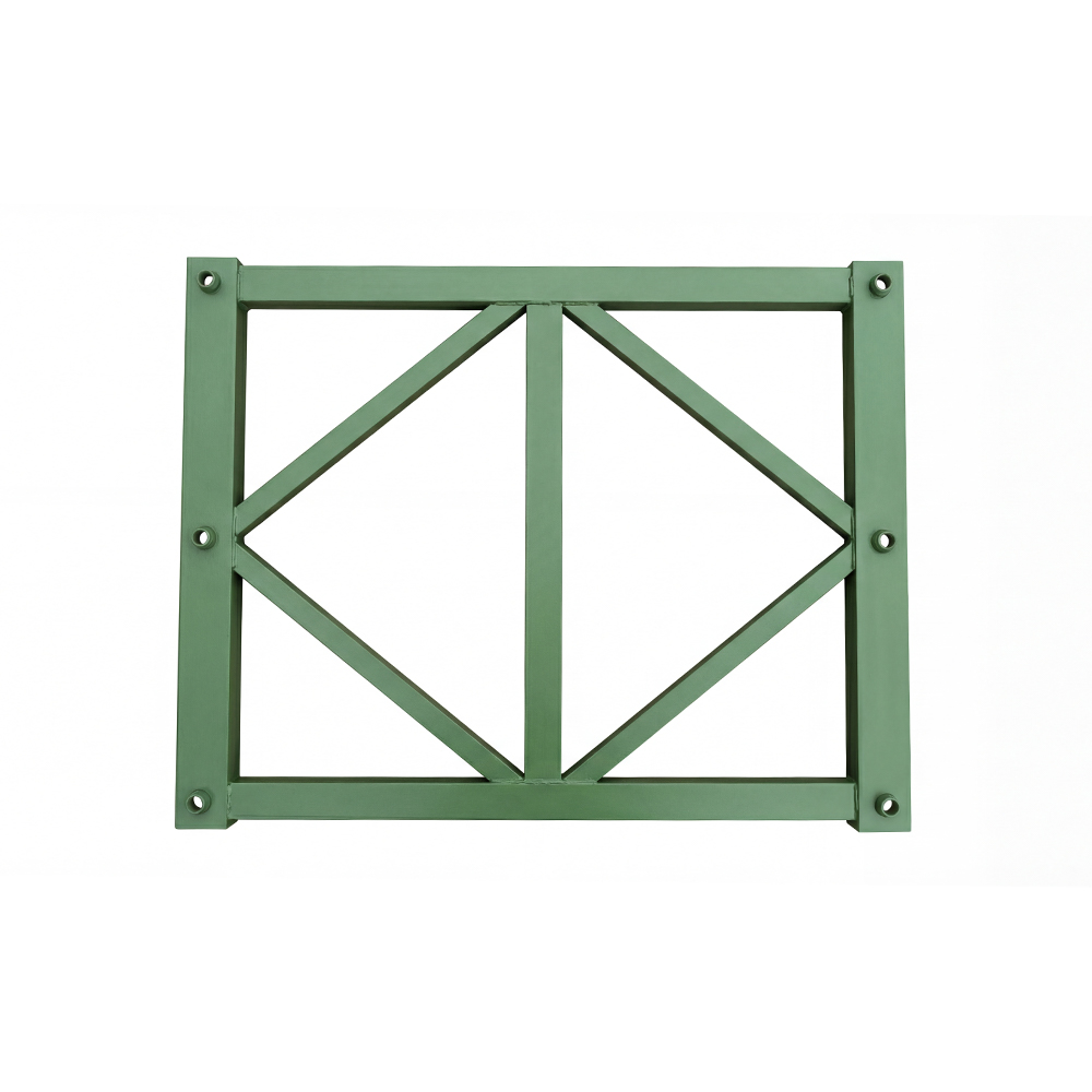
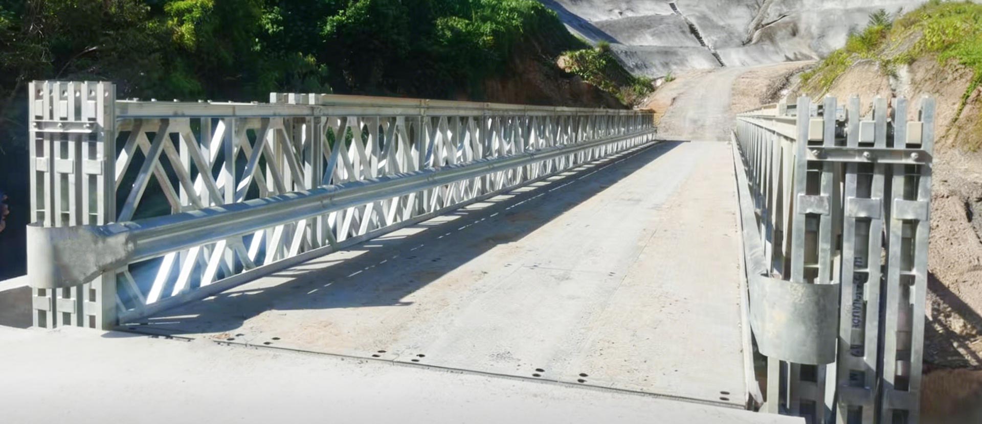
Puente tipo 200
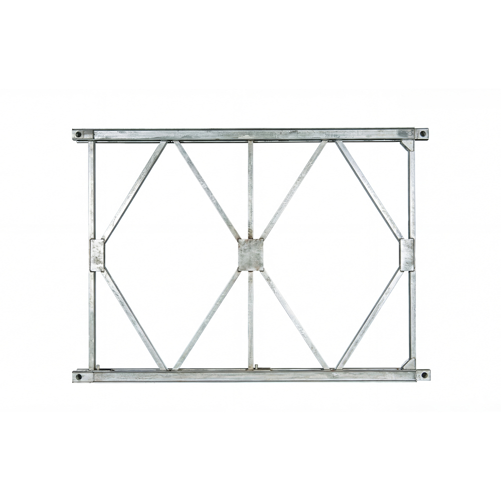
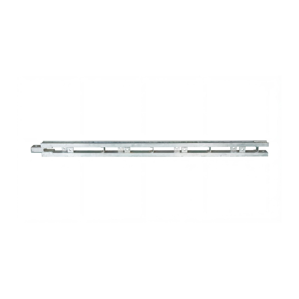
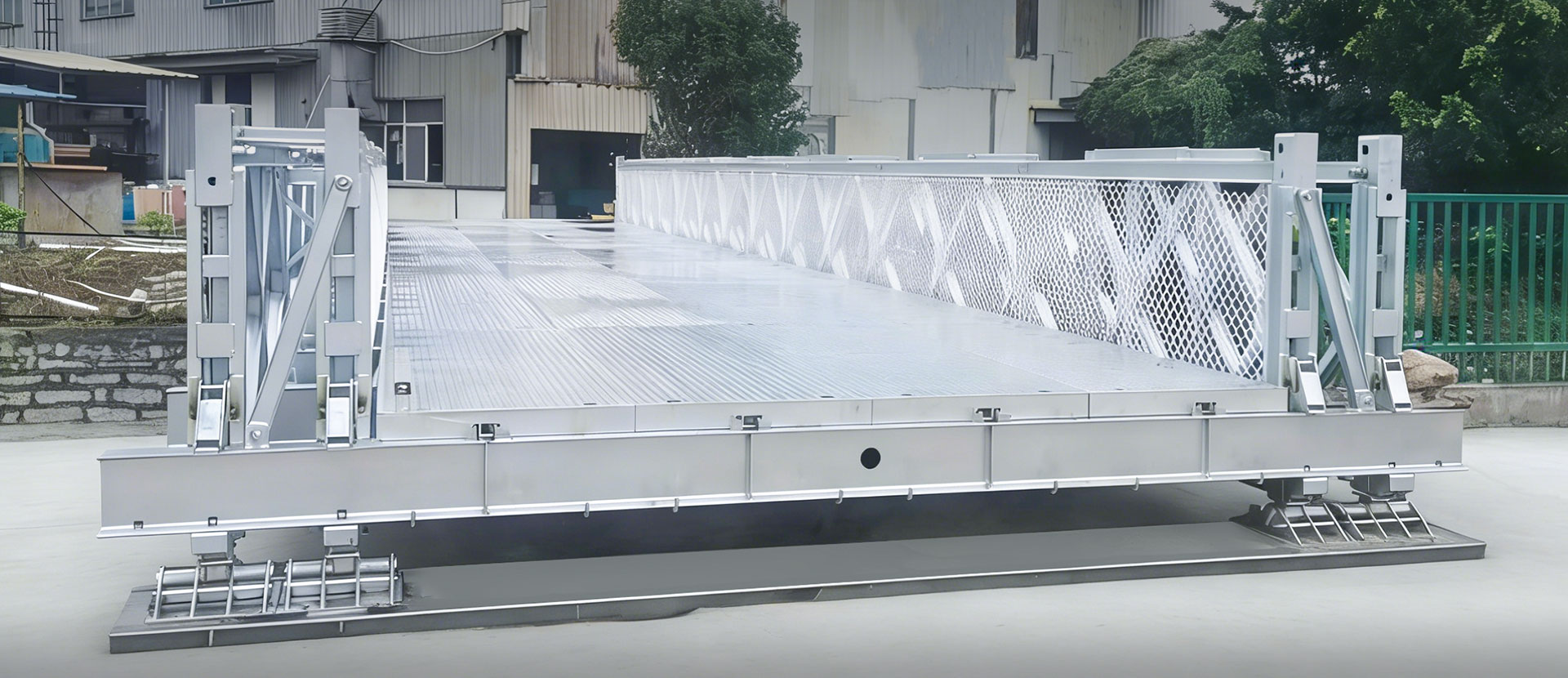
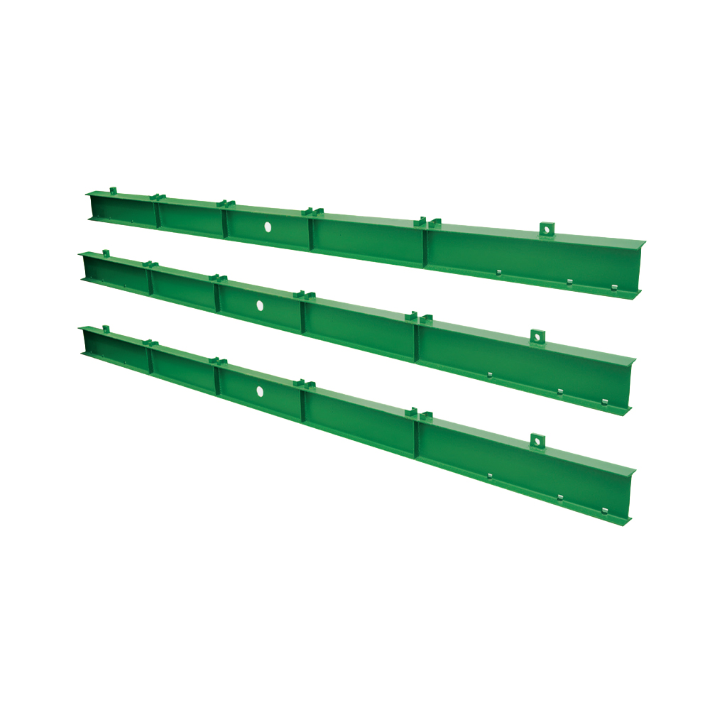
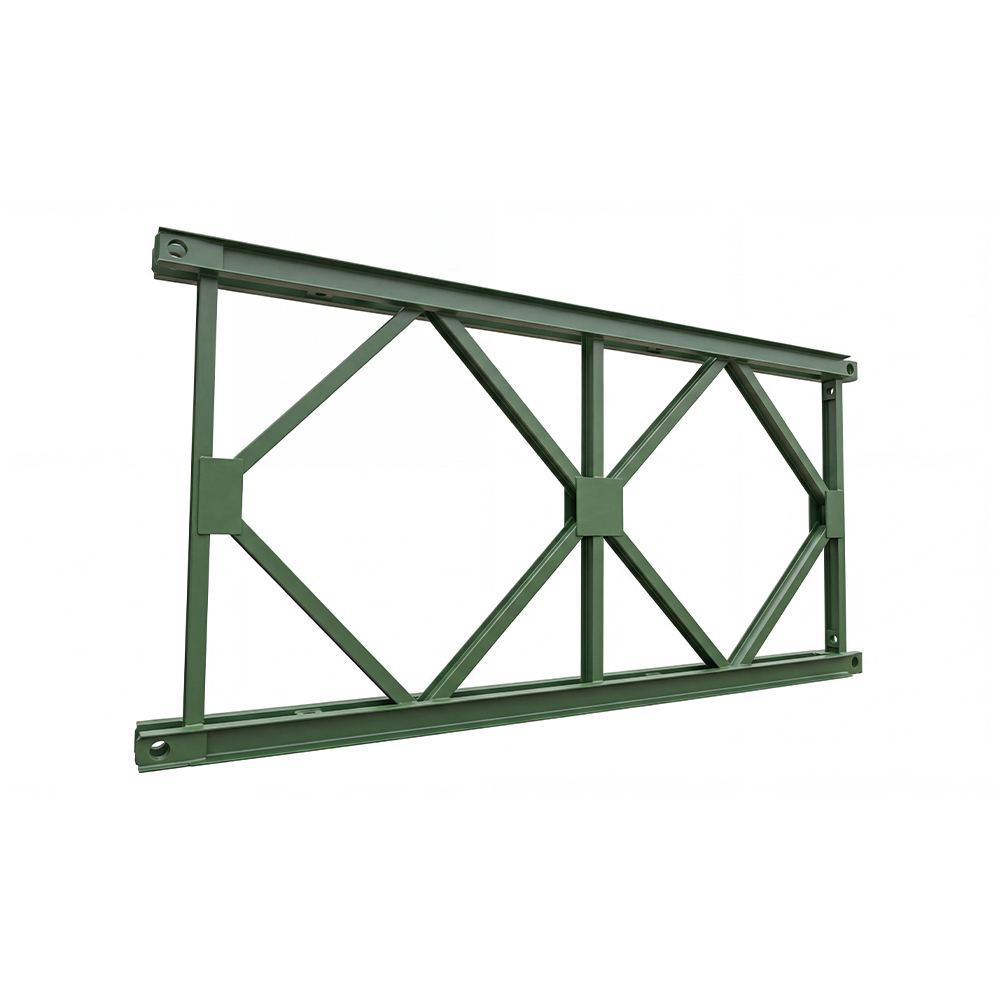
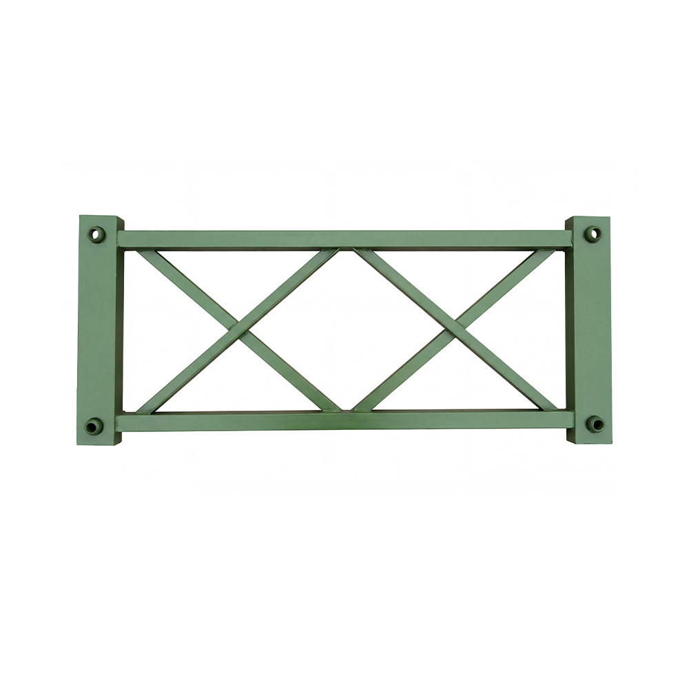
01
03
Proceso de producción
-
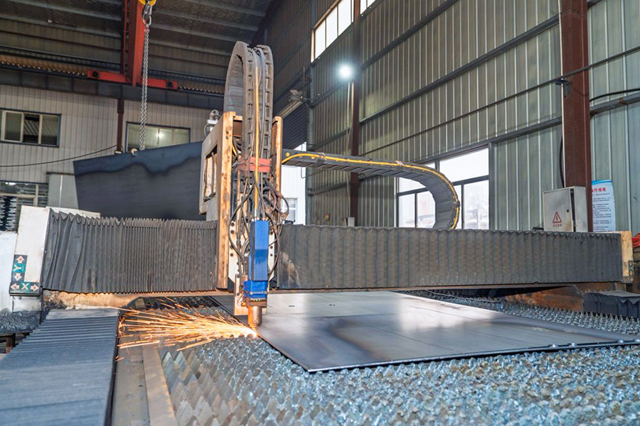
01. Láser
-
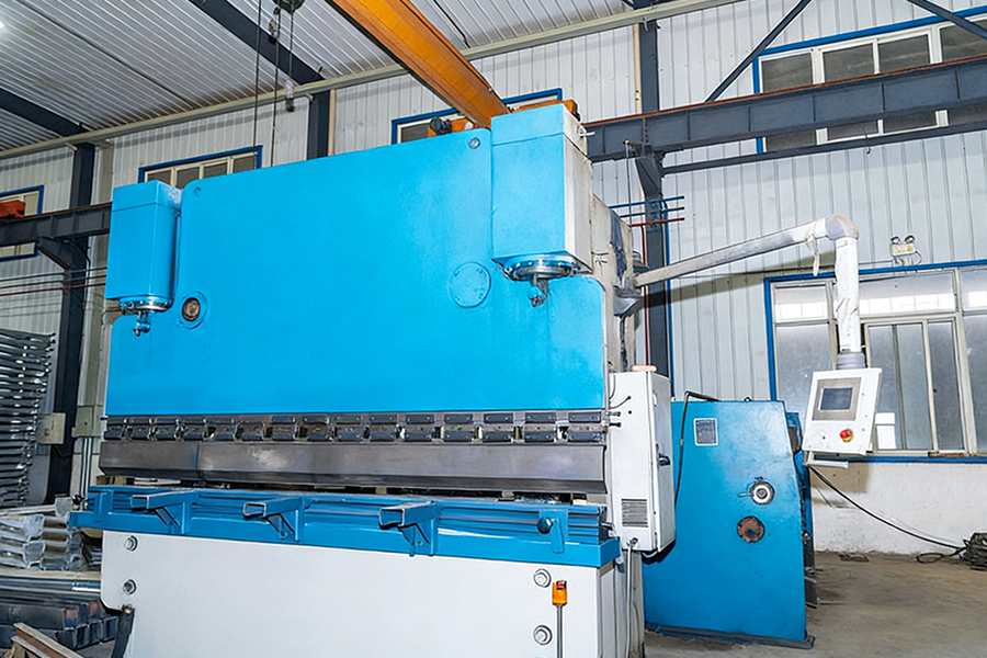
02. Doblado
-
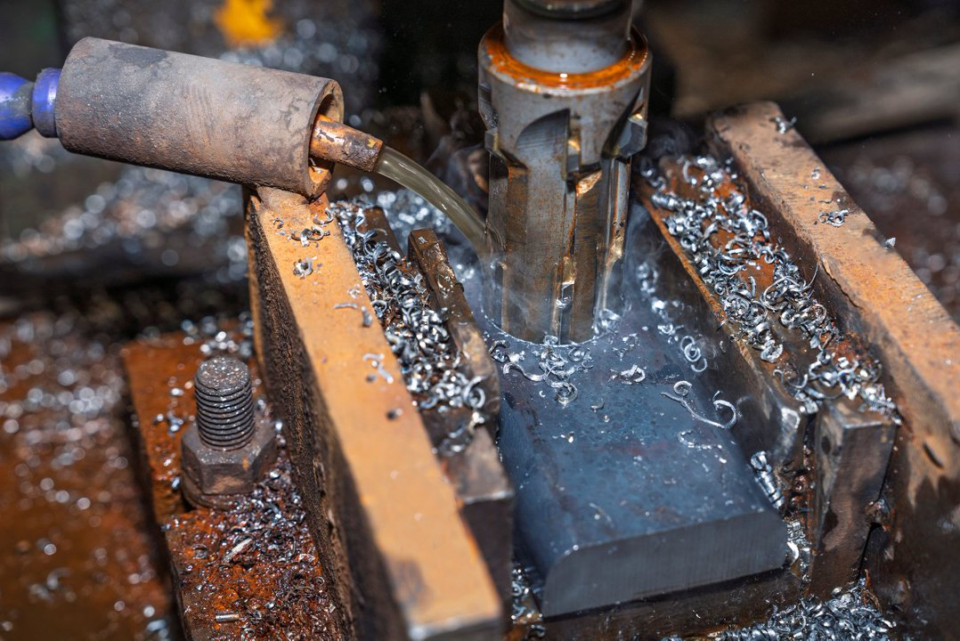
03. Punzonado
-
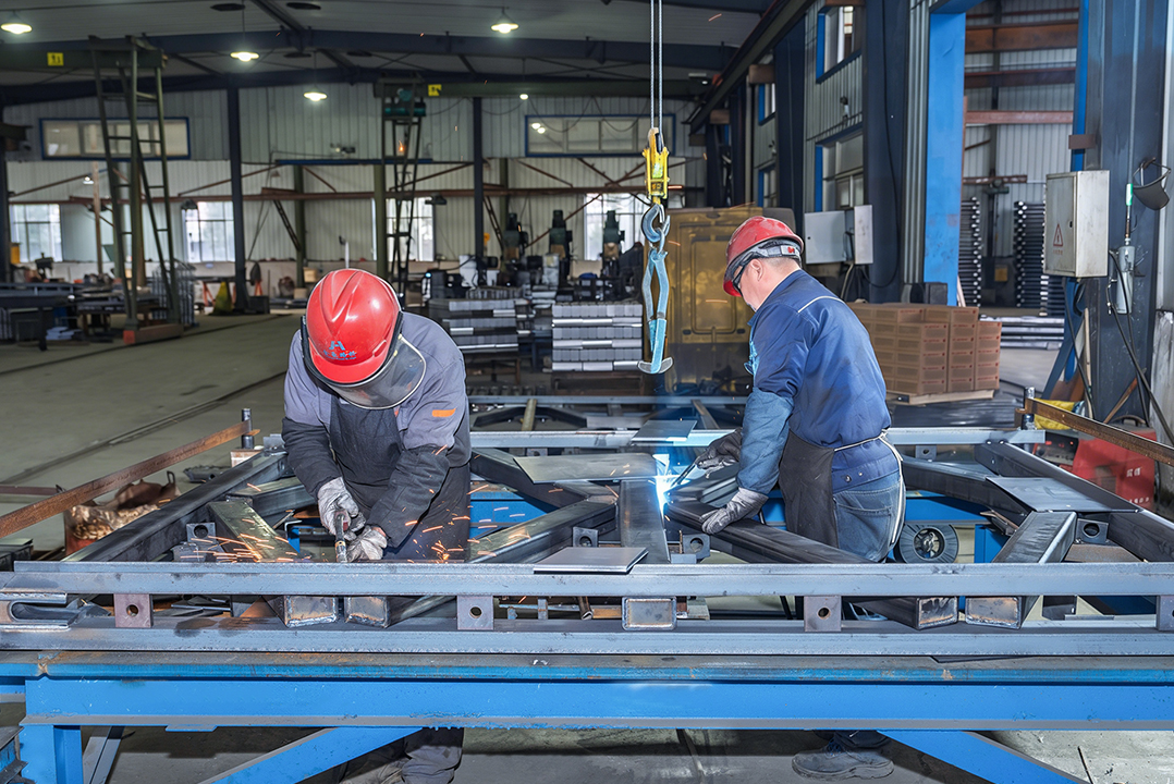
04. Asamblea
-
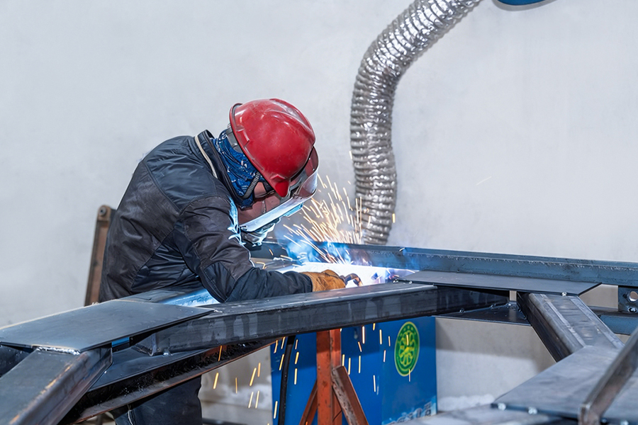
05. Soldadura
-
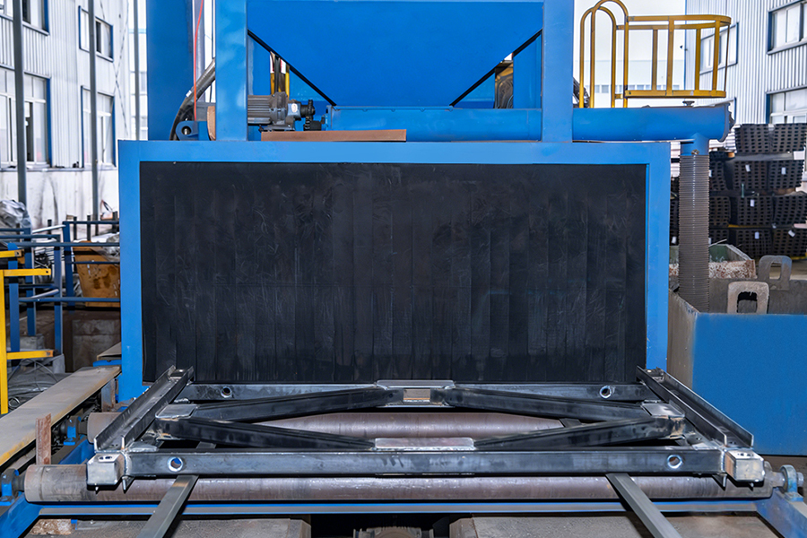
06. Explosión de disparo
-
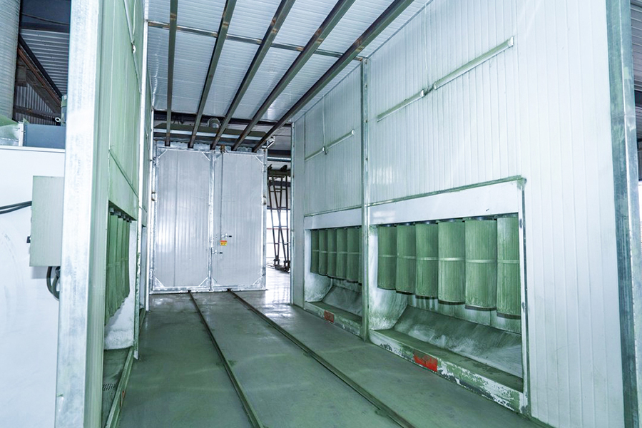
07. Pulverización de plástico
Ingeniería
Servicios
Según el tipo de puente, el tramo, los requisitos de carga y las condiciones del sitio, brindamos soluciones personalizadas para Bailey
puentes, caballetes de acero y sistemas de pórtico de lanzamiento.
-
01

Diseño de Ingeniería y Cálculo Estructural
 Carretera y puente Jinhao
-
02

Verificación de fabricación y premontaje
Carretera y puente Jinhao
-
03

Orientación y soporte técnico para la instalación in situ
Carretera y puente Jinhao
-
04

Gestión de proyectos y garantía de ejecución
Carretera y puente Jinhao
- Jinhao Road & Bridge
- Jinhao Road & Bridge
- Jinhao Road & Bridge
- Jinhao Road & Bridge
- Jinhao Road & Bridge
- Jinhao Road & Bridge
- Jinhao Road & Bridge
- Jinhao Road & Bridge
- Jinhao Road & Bridge
Últimas noticias
-
26Feb
JINHAO
Perfil de la empresa e historial de desarrollo
Zhenjiang Jinhao Road and Bridge Supporting Engineering Co., Ltd. está ubicada en el parque industrial de la ciudad de Shangdang, distrito de Dantu, ciudad de Zhenjiang. Junto al Gran Canal Beijing-Hangzhou y la autopista Yangli, estamos a solo 15 minutos en coche de la estación sur del ferrocarril de alta velocidad de Zhenjiang, que ofrece una ubicación privilegiada con un cómodo acceso al transporte. Fundada en 2017 con un capital registrado de 20,6 millones de yuanes, nuestra empresa se centró inicialmente en la comercialización profesional de materiales de construcción, materiales industriales y diversos materiales de procesamiento de metales. A medida que nuestro alcance comercial se expandió, nos transformamos con éxito en una empresa integral que integra el diseño, la fabricación, el montaje y el arrendamiento de puentes Bailey, cestas colgantes, encofrados de carrocerías de muelles y otros productos relacionados. Hoy en día, nuestra oferta principal incluye puentes de acero Bailey (tipo 321, tipo HD200), cestas colgantes triangulares, cestas colgantes de diamantes y una gama completa de encofrados de acero, que atienden a diversos sectores como transporte, ingeniería municipal y de conservación de agua. Defendemos el principio de “Calidad primero, excelencia profesional”, respaldado por un equipo dedicado de profesionales de ventas y gestión técnica. Ofrecemos soluciones de extremo a extremo, desde el diseño conceptual hasta la implementación del proyecto. Si tiene alguna consulta sobre productos, no dude en contactarnos por mensaje en línea o por teléfono. Esperamos asociarnos con usted para establecer nuevos puntos de referencia en ingeniería de construcción. -
26Feb
JINHAO
Productos principales y ventajas técnicas
Como nuestro producto estrella, el puente temporal de acero Bailey es un puente fabricado reconocido mundialmente, ampliamente implementado en proyectos de preparación para la defensa nacional, ingeniería de tráfico, ingeniería municipal, ingeniería de conservación de agua e ingeniería ferroviaria. Cuenta con una gama de características excepcionales: estructura simple, montaje conveniente, alta estandarización, fuerte intercambiabilidad, diversas formas estructurales, gran capacidad de carga y excelente aplicabilidad. Dependiendo de los requisitos de tramo, los puentes Bailey se pueden configurar de manera flexible como puentes temporales, puentes de emergencia o puentes semipermanentes para satisfacer diversas necesidades del proyecto. Además, las cerchas se pueden utilizar para formar estructuras de ingeniería y equipos para carreteras y puentes, como vigas guía, arcos, columnas de torres, perchas de pórtico, máquinas de montaje de puentes y encofrados para trepar edificios, lo que brinda soluciones eficientes y confiables para desafíos de ingeniería complejos. Nuestros puentes de acero Bailey se someten a un riguroso control de calidad durante todos los procesos de diseño y fabricación, cumpliendo con los estándares líderes de la industria para garantizar un rendimiento estable en condiciones extremas. Ya sea para operaciones de rescate de emergencia o proyectos de infraestructura a largo plazo, los puentes Jinhao Bailey son la opción confiable para soluciones de ingeniería confiables y eficientes. -
26Feb
JINHAO
Puentes de acero Bailey – La piedra angular de la infraestructura temporal y de emergencia moderna
Los puentes temporales de acero Bailey han sido durante mucho tiempo el estándar de oro en infraestructura temporal y de emergencia, reconocidos por su versatilidad y confiabilidad en proyectos de ingeniería globales. Desarrollados como una solución prefabricada, estos puentes son ahora indispensables en la preparación para el combate de defensa nacional, la ingeniería de tráfico, la construcción municipal, los proyectos de conservación de agua y el desarrollo ferroviario. Lo que distingue a los puentes Bailey son sus ventajas de diseño inherentes: una estructura simple que permite un ensamblaje rápido, una alta estandarización para una intercambiabilidad perfecta de los componentes y un marco robusto que ofrece una capacidad de carga excepcional. Estas cualidades permiten implementarlos rápidamente en zonas de desastre para restaurar la conectividad o utilizarlos como cruces temporales durante actualizaciones de infraestructura a gran escala. Dependiendo de los requisitos del proyecto, se pueden configurar en puentes temporales, de emergencia o semipermanentes de distintos tramos, adaptándose perfectamente a diversas condiciones ambientales y operativas. Más allá de su uso principal como puentes, las cerchas Bailey también se reutilizan ingeniosamente para formar vigas guía, arcos de soporte, columnas de torre, perchas de pórtico e incluso máquinas de montaje de puentes. Esta multifuncionalidad los convierte en una solución rentable y flexible para desafíos de ingeniería complejos, consolidando su papel como piedra angular de la resiliencia de la infraestructura moderna. -
26Feb
JINHAO
La excelencia en ingeniería de los puentes de acero Bailey – Diseño, aplicaciones y potencial futuro
El puente de acero Bailey es un triunfo del ingenio de la ingeniería, que combina la simplicidad del diseño con un rendimiento extraordinario. Su naturaleza modular y prefabricada permite fabricar secciones fuera del sitio y transportarlas incluso a los lugares más remotos, donde se ensamblan rápidamente sin necesidad de equipo pesado. Esta eficiencia es fundamental en escenarios sensibles al tiempo, como la recuperación posterior a un desastre o las operaciones militares. Diseñados para brindar durabilidad, los puentes Bailey cuentan con componentes de acero de alta resistencia que resisten la corrosión y soportan condiciones climáticas extremas, lo que garantiza un rendimiento a largo plazo incluso en entornos hostiles. Su diseño estandarizado también simplifica el mantenimiento y el reemplazo, reduciendo los costos del ciclo de vida para los propietarios de proyectos. De cara al futuro, el futuro de los puentes Bailey reside en su integración con materiales avanzados y tecnologías inteligentes. Las innovaciones en aleaciones ligeras y recubrimientos resistentes a la corrosión están ampliando su vida útil, mientras que las herramientas de modelado digital están optimizando su diseño para condiciones de carga específicas. A medida que evolucionen las demandas de infraestructura, los puentes Bailey seguirán adaptándose y seguirán siendo una solución vital para construir comunidades resilientes y conectadas en todo el mundo. -
14May
JINHAO
¿Qué encofrado debería elegir?
Cuando los ingenieros y contratistas evalúan el encofrado para la construcción de puentes, la elección entre encofrado de acero para puentes y el encofrado de aluminio rara vez es sencillo. Ambos sistemas están diseñados para resistir las importantes presiones hidrostáticas del hormigón húmedo en los elementos de los puentes (remates de pilares, plafones de plataformas, muros de estribo, muros laterales y crucetas), pero logran sus límites de rendimiento a través de propiedades de materiales, enfoques de fabricación y estrategias de implementación fundamentalmente diferentes. El encofrado de acero para puentes ha sido el estándar de la industria para infraestructura a gran escala durante décadas, apreciado por su rigidez bajo altas presiones de concreto, su estabilidad dimensional en temperaturas extremas y su capacidad de fabricarse en formas personalizadas para geometrías de puentes no estándar. El encofrado de aluminio, por el contrario, surgió como una alternativa sistemática que prioriza la reducción de peso y la inmunidad a la corrosión, cualidades que brindan beneficios compuestos en proyectos de larga duración con amplios requisitos de encofrado repetitivo. La decisión entre los dos sistemas es, en última instancia, una optimización técnica y económica específica de la geometría, el programa, las condiciones del sitio y el modelo de contratación de cada proyecto. Este artículo examina cada sistema en profundidad en todas las dimensiones que importan en la construcción de puentes y proporciona un marco estructurado para tomar la decisión correcta. 3× Más pesado que el aluminio (por m²) 500 Ciclos de reutilización (acero) 65% Ahorro de peso frente al acero 400 Ciclos de reutilización (aluminio) Encofrado de acero para puentes: propiedades de ingeniería y rendimiento Los sistemas de encofrado de acero para puentes se construyen a partir de secciones de acero estructural, generalmente de grado S235 a S355, con láminas frontales laminadas en frío que varían de 3 mm a 6 mm de espesor. El alto módulo elástico del acero (aproximadamente 200 GPa) produce una lámina frontal que se desvía mínimamente bajo la presión lateral del hormigón húmedo, incluso en paneles de gran formato que abarcan anchos significativos sin soporte intermedio. Capacidad estructural bajo condiciones de carga del puente. Los elementos de hormigón de puentes imponen algunos de los regímenes de presión más exigentes en la construcción. Los cabezales de muelle y las crucetas a menudo se vierten monolíticamente a alturas significativas, generando presiones hidrostáticas que superan los 80 kN/m² en la base. El encofrado de sofito de plataforma debe soportar no sólo la presión del concreto húmedo sino también la carga muerta superpuesta de las jaulas de refuerzo, el tráfico de la construcción y las fuerzas de oleaje de la línea de bombeo. El encofrado de acero, con su alto límite elástico y rigidez, maneja estas cargas combinadas con deflexiones más pequeñas y menor riesgo de distorsión del panel que las alternativas más livianas. Estabilidad térmica La construcción de puentes frecuentemente implica vertidos durante temperaturas extremas: vertidos de invierno en climas fríos con aislamiento de manta de curado y vertidos de verano que requieren gestión térmica para evitar un aumento temprano de resistencia. El encofrado de acero mantiene la estabilidad dimensional en un amplio rango de temperaturas. Su coeficiente de expansión térmica de aproximadamente 12 × 10⁻⁶ /°C está bien caracterizado y se tiene en cuenta en el diseño de juntas. Fundamentalmente, el acero no se desplaza ni se deforma bajo carga sostenida a temperaturas de construcción, una confiabilidad esencial para mantener las tolerancias en los asientos de los cojinetes y la geometría del borde de la plataforma. Soldabilidad y fabricación a medida. La soldabilidad del acero estructural es la ventaja definitoria de la geometría de puentes no estándar. Las formas de plafones curvos, los muros de contrafuerte sesgados, las tapas de pilares acartonadas y las secciones de plataforma alvadas requieren encofrados que no se pueden ensamblar únicamente a partir de paneles planos estándar. El acero se puede cortar, doblar y soldar in situ o en un taller de fabricación para que coincida con precisión con cualquier geometría. Esta flexibilidad es indispensable en proyectos de puentes exclusivos donde la ambición arquitectónica impulsa formas concretas complejas. Resistencias del acero en el uso de puentes Máxima rigidez bajo altas presiones hidrostáticas. Fabricación ilimitada a medida para geometrías curvas e irregulares. Máxima rigidez de la lámina frontal: deflexión mínima en plafones de gran luz. Vida útil comprobada de 500 ciclos en sistemas bien mantenidos. Resistencia superior al daño por impacto en sitios de puentes congestionados. Limitaciones del acero en el uso de puentes Los pesos de paneles de 45 a 80 kg/m² exigen un manejo asistido por grúa para todos los paneles, excepto los más pequeños. El riesgo de corrosión en entornos de puentes marinos y costeros requiere un mantenimiento continuo. Un mayor tonelaje de transporte aumenta los costos logísticos en sitios remotos o de acceso restringido. Un sistema más pesado ralentiza los ciclos de formación repetitivos. Encofrado de aluminio: propiedades de ingeniería y rendimiento Los sistemas de encofrado de aluminio utilizan aleaciones de aluminio de alta resistencia (más comúnmente 6061-T6 o 6082-T6) extruidas en marcos de paneles y láminas frontales con un espesor típico de 4 a 6 mm para la placa frontal y nervaduras de extrusión de 50 a 100 mm de profundidad para la profundidad estructural. El módulo elástico del aluminio es aproximadamente 70 GPa (un tercio del del acero), lo que significa que los diseños de paneles compensan mediante una geometría de sección más profunda e intervalos de nervaduras más espaciados para lograr una rigidez de la lámina frontal equivalente. Ventaja de peso y sus efectos posteriores. La densidad del aluminio (2.700 kg/m³) es aproximadamente un tercio de la del acero (7.850 kg/m³). En los paneles de encofrado, esto se traduce en una reducción de peso de aproximadamente entre un 60% y un 65% por metro cuadrado para un rendimiento estructural equivalente. Para la construcción de puentes, esto tiene profundas consecuencias operativas. Los paneles que pesan entre 15 y 25 kg/m² se pueden manipular manualmente o con polipastos de material liviano, lo que reduce significativamente la dependencia de la grúa. En proyectos de puentes donde la disponibilidad de grúas es una limitación crítica del camino, particularmente durante la construcción de plataformas sobre tráfico vivo o agua, la capacidad de manejar el encofrado sin la grúa es una ventaja del programa que puede compensar el costo adicional del material del aluminio. Inmunidad a la corrosión en entornos de puentes Los puentes se encuentran entre los entornos de construcción más corrosivos y exigentes. El aire marino salado, las zonas de salpicadura de marea, la escorrentía de deshielo cargada de cloruro y los espacios confinados permanentemente húmedos debajo de los plafones de las cubiertas crean condiciones que atacan agresivamente al acero desprotegido. La capa pasiva de óxido del aluminio proporciona una resistencia inherente a la corrosión sin necesidad de pintar ni recubrir constantemente. En proyectos de puentes costeros, la ventaja del costo del ciclo de vida del encofrado de aluminio sobre el acero se amplifica significativamente cuando se incluyen los costos de mantenimiento en la comparación. Precisión de extrusión y acabado superficial. Las tolerancias de extrusión de aluminio son más estrictas que las que se pueden lograr mediante la fabricación y el laminado de acero. Las caras de los paneles se pueden extruir con una variación de espesor de ±0,3 mm y las dimensiones del marco se controlan con una precisión submilimétrica. Esta precisión de fabricación produce conjuntos de paneles con tolerancias de unión inherentemente más estrictas, lo que reduce la pérdida de lechada y los defectos de las aletas de la superficie que requieren reparación en las caras de concreto expuestas de los puentes. Fortalezas del aluminio en el uso de puentes La reducción de peso del 60 al 65 % permite la manipulación manual y el uso reducido de la grúa. La resistencia natural a la corrosión elimina el costo del ciclo de vida de volver a recubrir en ambientes marinos. Tolerancias de extrusión más estrictas mejoran la calidad del acabado de la superficie del hormigón. Ciclos de reutilización más rápidos en elementos de puentes repetitivos. Menor tonelaje de transporte en vías de acceso remotas o con restricciones de peso. Limitaciones del aluminio en el uso de puentes No se puede soldar in situ con equipo estándar; las formas personalizadas requieren una fabricación especializada. Una menor resistencia al impacto significa que es más probable que se dañen los paneles en entornos congestionados de construcción de puentes. Mayor coste de material por tonelada. El coeficiente de expansión térmica (23 × 10⁻⁶/°C) es casi el doble que el del acero; requiere un diseño cuidadoso de las juntas en condiciones de temperatura variable. Comparación integral de rendimiento La siguiente matriz evalúa ambos sistemas en todo el conjunto de criterios relevantes para los equipos de proyectos de construcción de puentes, desde la ingeniería estructural hasta la logística, la sostenibilidad y las adquisiciones. Criterio de evaluación Encofrado de acero para puentes Encofrado de aluminio Veredicto Capacidad de carga (vertidos a alta presión) Excelente: hasta 120 kN/m² Bueno: hasta 80 kN/m² Acero Peso/manipulación del panel 45–80 kg/m²: se requiere grúa 15–28 kg/m²: manual factible Aluminio Fabricación de formas a medida Capacidad total de soldadura in situ Sólo taller especializado Acero Resistencia a la corrosión Requiere recubrimiento y mantenimiento. Inherente: no necesita mantenimiento Aluminio Acabado de superficie de hormigón F2-F4 alcanzable F3–F4 consistentemente Aluminio (slight edge) Control de rigidez/deflexión Módulo más alto: menos deflexión Compensado por secciones más profundas. Acero Velocidad de montaje (repetitivo) Moderado: dependencia de la grúa Rápido: paneles más ligeros, menos grúa Aluminio Resistencia al impacto en el sitio Alto: tolera el manejo del sitio Más bajo: es más probable que se produzcan abolladuras Acero Vida útil del ciclo de reutilización 300–500 ciclos 250–400 ciclos Acero (slight edge) Peso Transporte / Logística Alto tonelaje 60-65 % de ahorro de peso Aluminio Costo de capital inicial Menor por tonelada Más alto por tonelada Acero Costo del ciclo de vida (incluido mantenimiento) Mayor (costos de corrosión) Más bajo en ambientes marinos Aluminio (marine) Rendimiento en climas fríos Estable: expansión predecible Mayor expansión: gestión conjunta Acero Sostenibilidad / Fin de vida Reciclable Reciclado de alto valor: mejor recuperación Aluminio Análisis de aplicaciones específicas de puentes Los diferentes elementos del puente presentan diferentes desafíos en el encofrado. La elección óptima del material a menudo varía según el tipo de elemento dentro de un solo proyecto de puente, lo que hace que una especificación híbrida sea cada vez más común en grandes proyectos de infraestructura. Columnas de muelle y conformación de fuste. Las columnas de pilares circulares y rectangulares se encuentran entre las aplicaciones de formación de puentes de mayor presión, con alturas de vertido que frecuentemente exceden los 6 a 8 metros para las principales estructuras de viaductos. La presión hidrostática en la base de un vertido de hormigón de densidad normal de 8 metros alcanza aproximadamente 90–95 kN/m², una carga que empuja los sistemas de aluminio a su capacidad nominal o más allá de ella, mientras se mantiene dentro del cómodo rango operativo del encofrado de acero de ingeniería. Para columnas de pilares altas y muy cargadas, el encofrado de acero es la especificación técnicamente adecuada. Los sistemas trepadores de aluminio se pueden utilizar en pilares de altura moderada donde no se exceden los índices de presión. Conformación de tapa de muelle y cruceta Las tapas de muelle concentran una carga significativa: el peso del hormigón húmedo, el refuerzo y el peso propio del encofrado se combinan en el encofrado del sofito. La compleja geometría de la mayoría de las tapas de los pilares (con plafones acaricados, anchos variables y detalles de ménsulas) exige un encofrado hecho a medida que solo se puede lograr de manera económica en acero. El encofrado de aluminio para pilares se fabrica para secciones transversales rectangulares estándar en estructuras de viaductos repetitivos, pero rara vez es práctico para geometrías distintivas o complejas. Formación de plafones de cubierta El encofrado del plafón de la plataforma del puente se extiende entre las tapas de los pilares y debe soportar una carga distribuida sustancial desde la losa de la plataforma de concreto húmeda que se encuentra arriba. Aquí, la ventaja del aluminio se vuelve más convincente: el menor peso de los paneles de aluminio reduce la demanda estructural sobre la cimbra que los soporta, y la velocidad de manipulación de los paneles afecta directamente la ruta crítica del ciclo de vertido de la plataforma. En viaductos largos con 30 o más tramos repetitivos, el ahorro acumulativo del programa gracias al encofrado más rápido del plafón se puede medir en semanas. Formación de pilares y paredes de ala Los estribos de puentes implican altos volúmenes de hormigón, alturas de vertido significativas y, a menudo, disposiciones de refuerzo congestionadas que complican el montaje y el cebado del encofrado. El encofrado de acero, con su superior resistencia al impacto y modificabilidad en el sitio, soporta las condiciones impredecibles de la construcción de pilares de manera más robusta que el aluminio. Las paredes de las alas, particularmente en los estribos sesgados, requieren ajustes angulares complejos que se logran más fácilmente en conjuntos de acero soldado que en conjuntos de aluminio extruido. "La estrategia de encofrado de puentes más efectiva rara vez es una elección binaria: los contratistas experimentados especifican cada vez más acero para elementos personalizados de alta presión y aluminio para aplicaciones repetitivas de menor presión en el mismo proyecto, extrayendo las ventajas de ambos sistemas donde cada uno sobresale". Índice de costo relativo indicativo basado en puntos de referencia de la industria. Las cifras reales varían según la escala del proyecto, la ubicación y el modelo de adquisición. TCO = Costo total de propiedad. La prima del coste de capital del aluminio (normalmente entre un 60% y un 80% más alta que el encofrado de acero equivalente por metro cuadrado) es la línea más visible en la comparación de adquisiciones. Sin embargo, esta brecha inicial se reduce considerablemente cuando se incluyen los costos de mano de obra, grúas y transporte. En un gran proyecto de puente con 5.000 m² de plafón que forma más de 40 tramos repetitivos, la reducción en los levantamientos de grúa que se puede lograr con paneles de aluminio puede representar ahorros de costos que compensan una parte significativa de la prima del material dentro de los primeros dos o tres ciclos de vertido. Nota sobre modelos financieros Los modelos de costos del ciclo de vida para el encofrado de puentes deben incluir el valor residual al final de su vida útil: la aleación de aluminio de alta pureza retiene aproximadamente entre el 40% y el 60% de su valor material original como material reciclado, mientras que el encofrado de acero usado tiene precios de chatarra más bajos. Para los programas de infraestructura de larga duración, esta diferencia en el valor terminal es financieramente importante en el caso de la inversión en aluminio. Consideraciones ambientales y de sostenibilidad Los clientes de infraestructura están incorporando cada vez más métricas de sostenibilidad en las decisiones de adquisición de encofrados, impulsados por compromisos de construcción netos cero y la creciente prevalencia de requisitos de declaración ambiental de producto (EPD) en los contratos de puentes. Comparación de carbono incorporado La producción de aluminio primario consume mucho carbono: aproximadamente de 8 a 12 kg de CO₂ equivalente por kg de metal, en comparación con aproximadamente 1,8 a 2,2 kg de CO₂e/kg para el acero primario. Tal como se fabrica, el encofrado de aluminio conlleva una mayor huella de carbono incorporada que el encofrado de acero equivalente. Sin embargo, este cálculo cambia sustancialmente cuando se utiliza aluminio secundario (reciclado): la producción de aluminio reciclado consume solo el 5% de la energía de la producción primaria, lo que reduce el carbono incorporado a aproximadamente 0,5 a 0,7 kg de CO₂e/kg, por debajo del del acero. Amortización del carbono del ciclo de reutilización El impacto ambiental por vertido de hormigón disminuye con cada ciclo de reutilización. Dividido en 400 vertidos, el carbono incorporado por ciclo de cualquiera de los sistemas se vuelve mínimo. La variable de sostenibilidad dominante en el sitio no es el material de encofrado sino la logística del transporte: el ahorro de peso de entre un 60% y un 65% de los paneles de aluminio reduce el consumo de combustible en el transporte y las operaciones de grúas en el sitio, contribuyendo significativamente a proyectar los presupuestos de carbono en grandes proyectos de puentes. Especifique las aleaciones de aluminio secundarias cuando estén disponibles: Muchos fabricantes de encofrados ofrecen ahora sistemas que incorporan palanquillas con alto contenido reciclado, lo que reduce sustancialmente el carbono incorporado sin comprometer el rendimiento estructural. Maximizar el recuento de ciclos de reutilización: El mantenimiento y la limpieza adecuados después de cada vertido es la acción de sostenibilidad de mayor impacto para cualquiera de los sistemas: cada ciclo adicional amortiza aún más la huella de fabricación. Planificar el reciclaje al final de su vida útil: Tanto el acero como el aluminio son infinitamente reciclables; Garantizar que los contratos de adquisición especifiquen las obligaciones de recuperación de materiales al final de la vida útil del encofrado. Cuenta para ahorros de combustible en grúas: La ventaja de peso del aluminio reduce las horas de funcionamiento del equipo; inclúyalo en la contabilidad de carbono del proyecto para reflejar el panorama completo del ciclo de vida. Marco de decisión: ¿Qué sistema para qué proyecto? En lugar de tratar esto como una única decisión binaria, los equipos de proyecto deben utilizar el siguiente marco para seleccionar el sistema (o combinación) apropiado para las condiciones específicas de su proyecto de puente. Elija encofrado de acero cuando... Las presiones del hormigón superan los 80 kN/m² (pilas altas, estribos profundos) La geometría del puente es compleja, no estándar o muy variable. La capacidad de soldadura y modificación in situ es esencial El entorno del sitio implica plantas pesadas, riesgo de impacto y manejo brusco. El presupuesto de capital es limitado y se prioriza el costo inicial El entorno no marino ni costero minimiza los costos del ciclo de vida de la corrosión Los requisitos de formación no son repetitivos y tienen una oportunidad de reutilización limitada. Las temperaturas extremas requieren una variación dimensional mínima en el encofrado Elija encofrado de aluminio cuando... Un viaducto largo con 20 tramos repetitivos maximiza el valor de reutilización El entorno marino, costero o de mareas hace que la corrosión sea un factor de costo del ciclo de vida La disponibilidad de grúas es una limitación crítica en el programa del puente. Las restricciones de acceso limitan el peso de los vehículos de transporte al recinto Las clasificaciones de presión de formación de plafones están dentro del diseño del aluminio. Se especifica la calidad de la superficie del hormigón arquitectónico F3–F4 Las credenciales de sostenibilidad y la operación de bajo mantenimiento son las prioridades del cliente La velocidad del programa en el conformado de la plataforma es el impulsor comercial dominante Una especificación híbrida (acero para pilares y estribos, aluminio para plafones de plataformas) es cada vez más la solución de ingeniería preferida en los principales contratos de puentes. Este enfoque asigna cada material a las aplicaciones donde sus propiedades específicas ofrecen la mayor ventaja, en lugar de imponer las limitaciones de un sistema en toda la estructura. Adquisiciones, estándares y garantía de calidad La adquisición de encofrados para puentes debe realizarse dentro de un marco riguroso de garantía de calidad. Tanto los sistemas de acero como los de aluminio utilizados en los contratos de puentes de infraestructura pública están sujetos a la aprobación formal del diseño de obras temporales, la certificación de materiales y protocolos de inspección que difieren en varios aspectos importantes entre los dos materiales. Normas aplicables En los mercados europeos, el diseño de encofrados de puentes se rige por la norma EN 12812 (Cifra: requisitos de rendimiento y diseño general) como marco general, respaldada por la norma EN 13670 para la ejecución de construcciones de hormigón. Los paneles de encofrado de acero deben fabricarse según las normas de materiales EN 10025 (acero estructural) y, para láminas frontales, EN 10131 (acero laminado en frío). Los sistemas de aluminio están certificados según EN 485 (láminas y tiras de aluminio y aleaciones de aluminio) y EN 755 (perfiles de aluminio extruido). En EE. UU., ACI 347 proporciona el estándar de referencia para el diseño e inspección de encofrados de hormigón. Pruebas de carga de terceros Para aplicaciones de puentes donde las presiones del concreto se acercan o exceden las clasificaciones estándar del panel, las especificaciones de adquisición deben requerir certificados de prueba de carga de terceros que demuestren el desempeño del panel a la presión de diseño específica del proyecto con factores de seguridad apropiados. Tanto los fabricantes de sistemas de calidad de acero como de aluminio suministran documentación de prueba; Los compradores deben tener cuidado con los productos en los que dicha documentación no esté disponible o no pueda verificarse de forma independiente. Inspección y trazabilidad Los contratos de infraestructura de puentes requieren cada vez más la trazabilidad del material: documentación que vincule los paneles de encofrado con los certificados de materiales, informes de pruebas de fábrica y registros de inspección de fabricación. Los paneles de encofrado de acero fabricados según EN 10204 Tipo 3.1 incluyen certificados de inspección emitidos por la acería. Los sistemas de extrusión de aluminio pueden certificarse de manera similar. Mantener estos registros como parte de la documentación de gestión de calidad del proyecto para la vida útil de diseño del puente. Encargue siempre un diseño de obras temporales: Ambos sistemas requieren un diseño de ingeniería formal por parte de un ingeniero de obras temporal competente para la carga de clase de puente; las tablas de carga del fabricante del sistema son el punto de partida, no el diseño. Verifique el estado del panel antes de cada implementación: Implementar una lista de verificación de inspección previa al uso documentada que cubra la integridad de la hoja frontal, la condición del mecanismo de bloqueo y la distorsión del marco, tanto para sistemas de acero como de aluminio. No mezcle generaciones de paneles sin la aprobación de ingeniería: Los paneles más antiguos que han excedido su número de ciclos nominales o han sufrido daños pueden tener una capacidad de carga reducida; mezclarlos con paneles clasificados en un banco de formación es un riesgo estructural Establecer protocolos de limpieza y almacenamiento antes de la movilización del sitio: La selección del agente desmoldante, el procedimiento de limpieza y la orientación del almacenamiento afectan directamente la calidad del acabado del concreto y la longevidad del sistema en proyectos de puentes. Evaluación final: Los encofrados de acero para puentes y los encofrados de aluminio son tecnologías complementarias, no competidoras. La capacidad de carga superior, la soldabilidad en sitio y la resistencia al impacto del acero lo convierten en la opción definitiva para los elementos geométricamente complejos de alta presión que definen la subestructura del puente. La ventaja de peso, la inmunidad a la corrosión y la precisión del acabado superficial del aluminio lo convierten en el sistema elegido para el encofrado repetitivo de plafones de plataformas de puentes, entornos marinos y aplicaciones críticas para programas donde la independencia de la grúa ofrece un valor cronograma mensurable. Los proyectos de puentes con mayor éxito técnico y comercial tratan esto como un ejercicio de selección de materiales (hacer coincidir las propiedades del sistema con los requisitos de los elementos) en lugar de una decisión de licitación binaria aplicada uniformemente en toda una estructura. -
21May
JINHAO
¿Qué hace que una armadura sea fuerte?
Cuyo los ingenieros y constructores preguntan ¿Qué diseño de armadura es el más fuerte? , la respuesta nunca es única. Fuerza del braguero Depende de la longitud del tramo, el tipo y dirección de la carga aplicada, el material utilizado y el propósito estructural específico. Dicho esto, ciertas geometrías de truss superan consistentemente a otras en una amplia gama de aplicaciones. Esta guía analiza los diseños de armaduras más comunes, explica la mecánica detrás de su resistencia e identifica a los de mejor desempeño para diferentes escenarios del mundo real. Una armadura es un marco estructural formado por miembros rectos conectados en uniones, llamados nodos. A diferencia de una viga sólida, una armadura logra resistencia a través de la geometría (la disposición de los triángulos) en lugar de solo a través de la masa. El triángulo es la única figura geométrica que no se puede deformar sin cambiar la longitud de uno de sus lados. , lo que lo hace inherentemente rígido y resistente a la carga. Cuando se aplica una carga a una armadura, la fuerza se distribuye a través de los miembros como tensión (fuerzas de tracción) o compresión (fuerzas de empuje). La eficiencia del diseño de una armadura se mide por qué tan bien distribuye estas fuerzas con un mínimo de material. Una armadura fuerte: Convierte las cargas aplicadas en fuerzas axiales puras (tensión o compresión) a lo largo de sus miembros. Minimiza los momentos de flexión, que son mucho más dañinos estructuralmente que las fuerzas axiales. Distribuye la carga uniformemente entre varios miembros en lugar de concentrar la tensión en un punto Utiliza las longitudes de miembro más cortas posibles para resistir el pandeo bajo compresión. Logra la máxima profundidad estructural en relación con la longitud del tramo. Con estos principios en mente, queda claro por qué algunas configuraciones de truss sobresalen en escenarios específicos mientras que otras se quedan cortas. La geometría de cada diseño determina qué tan bien se cumplen estos criterios. Explicación de los diseños de armaduras más comunes Antes de determinar cuál es el más resistente, es esencial comprender cómo se construye cada tipo de armadura principal y cómo fluyen las fuerzas a través de él. braguero Pratt La armadura Pratt, patentada por Thomas y Caleb Pratt en 1844, presenta miembros verticales bajo compresión y miembros diagonales bajo tensión . Las diagonales se inclinan hacia abajo hacia el centro del tramo desde cada extremo de soporte. Debido a que el acero y la mayoría de los materiales estructurales manejan la tensión de manera mucho más eficiente que la compresión, la armadura Pratt hace un uso excelente de su material. Es uno de los diseños de armaduras más utilizados en puentes, sistemas de techos y edificios industriales que abarcan de 18 a 90 metros (60 a 300 pies). braguero de howe La armadura Howe invierte la configuración Pratt: su Los miembros diagonales están bajo compresión y sus miembros verticales están bajo tensión. . Las diagonales se inclinan hacia arriba hacia el centro. Este diseño fue ventajoso en el siglo XIX, cuando la madera (que soporta bien la compresión) era el principal material estructural. En la construcción moderna de acero, la armadura Howe es menos eficiente que la Pratt porque coloca miembros más largos en compresión, lo que aumenta el riesgo de pandeo. Warren Truss La armadura Warren, desarrollada por James Warren en 1848, utiliza Triángulos equiláteros o isósceles sin miembros verticales. . Los miembros diagonales alternan entre tensión y compresión. Este diseño requiere menos miembros totales que Pratt o Howe, lo que reduce el costo y el peso del material. La armadura Warren funciona extremadamente bien bajo cargas en movimiento o distribuidas y es una opción dominante para puentes ferroviarios y de carreteras de gran luz. Una versión modificada, la armadura Warren con verticales, agrega miembros verticales para manejar cargas puntuales concentradas de manera más efectiva. K-truss La armadura K presenta miembros diagonales que se encuentran en el punto medio de los miembros verticales, formando una forma de K en cada panel. Esta configuración Reduce efectivamente a la mitad la longitud sin soporte de los miembros verticales. , aumentando drásticamente su resistencia al pandeo bajo compresión. La armadura K se usa ampliamente en la construcción de puentes de gran luz donde el pandeo de los miembros es una preocupación principal de diseño. Armadura Fink El truss Fink se caracteriza por una Subestructura en forma de V que divide el tramo en paneles triangulares más pequeños , transfiriendo eficientemente las cargas a los puntos de apoyo. Se utiliza principalmente en la construcción de tejados. Su geometría permite un uso económico del material en aplicaciones de techos inclinados, particularmente para luces residenciales y comerciales livianas de 6 a 20 metros (20 a 65 pies). Vierendeel Truss (Marco) El Vierendeel es técnicamente un marco rígido en lugar de una verdadera armadura, ya que carece de miembros diagonales. se basa en Conexiones resistentes a momento en cada junta. para transferir cargas. Si bien no es tan eficiente estructuralmente como las cerchas triangulares bajo carga simple, el Vierendeel se usa en arquitectura donde los miembros diagonales obstruirían el espacio funcional, como en sistemas de piso sobre áreas de planta abierta o en puentes peatonales. Armadura de cuerda de arco La armadura de cuerda del arco presenta una cuerda superior curva (el arco) y una cuerda inferior recta (la cuerda), con miembros de red verticales o diagonales entre ellos. La cuerda superior curvada sigue la forma parabólica del diagrama de momento flector. para una carga distribuida uniformemente, lo que significa que el material se coloca exactamente donde más se necesita. Esto hace que la cuerda de arco sea una de las formas de armadura con mayor eficiencia de materiales para aplicaciones de techos de luces largas. braguero de baltimore Una versión refinada del truss Pratt, el truss Baltimore añade submiembros que subdividen cada panel , reduciendo la longitud no soportada de los miembros comprimidos y permitiendo luces más largas sin aumentar el tamaño de los miembros. Se utiliza comúnmente en puentes de carreteras y ferrocarriles de gran luz donde es fundamental controlar el pandeo en el cordón de compresión principal. ¿Qué diseño de armadura es el más fuerte? A través de pruebas independientes de ingeniería estructural y estudios de carga académica, El truss Warren y el truss Pratt emergen consistentemente como los diseños más fuertes y eficientes. para la más amplia gama de aplicaciones. Sin embargo, cada uno conduce en diferentes condiciones. Más resistente para cargas distribuidas uniformemente: Warren Truss Para tramos que transportan cargas distribuidas uniformemente a lo largo de su longitud, como el peso muerto de una plataforma de techo o la carga viva uniforme de una plataforma de puente, la armadura Warren logra la mejor relación resistencia-peso. Su geometría de triángulo equilátero distribuye las fuerzas simétricamente, y ningún miembro soporta desproporcionadamente más estrés que otro . En pruebas controladas de carga hasta falla, las armaduras Warren hechas de materiales y dimensiones idénticas soportan consistentemente cargas más altas antes de fallar que las configuraciones equivalentes de Pratt o Howe bajo condiciones de carga uniformes. Más resistente para luces largas con cargas puntuales: Pratt Truss Cuando las cargas se concentran en puntos específicos, como vigas secundarias que se enmarcan en una armadura de puente principal, la armadura Pratt funciona mejor. Su configuración coloca a los miembros más largos (las diagonales) en tensión en lugar de compresión, eliminando el riesgo de pandeo en los miembros más críticos . Debido a que los miembros en tensión pueden adelgazarse sin riesgo de pandeo, el diseño de Pratt utiliza menos material para lograr una resistencia equivalente en condiciones de carga puntual que cualquier otro tipo de armadura. Más resistente para aplicaciones en techos: Fink o Bowstring Truss En la construcción de techos inclinados, la armadura Fink es el diseño con mayor eficiencia de materiales para luces de hasta aproximadamente 20 metros. Para luces de techo industriales y comerciales más largas, el La armadura de cuerda de arco es la configuración más fuerte. , porque su cuerda superior curvada se alinea con la distribución natural de tensiones de la carga, reduciendo las fuerzas internas en toda la estructura. Más fuerte contra el pandeo en miembros de compresión: K-Truss o Baltimore Truss Cuando el pandeo del miembro bajo compresión es el factor de diseño limitante (generalmente en tramos muy largos o cuando se utilizan miembros delgados de alta resistencia), la armadura K y la armadura Baltimore superan a otros diseños por Reducir a la mitad la longitud efectiva de pandeo de sus elementos de compresión verticales y diagonales. . Esto permite luces más largas con la misma sección transversal del miembro. Comparación de resistencia estructural: datos de prueba clave Numerosos estudios de ingeniería y competencias estudiantiles de construcción de puentes han producido datos de pruebas de carga comparativas para diseños de armaduras comunes. Si bien los resultados varían según el material, la escala y el protocolo de carga, los siguientes hallazgos generales están bien respaldados: braguero Warren logra consistentemente la relación carga-peso más alta bajo cargas distribuidas uniformemente, generalmente entre un 15 y un 25 % más fuerte por unidad de material que una configuración Howe equivalente. armadura Pratt supera a la armadura Howe entre un 10 y un 20% en condiciones de carga puntual en la construcción de acero, debido a los miembros diagonales de tensión dominante. braguero de howe supera a Pratt en la construcción con madera bajo cargas de compresión, donde la mayor resistencia a la compresión de la madera es una ventaja. Armazón de cuerda de arco puede lograr relaciones de luz a profundidad de 8:1 a 10:1 mientras mantiene la eficiencia estructural, superior a los diseños de armazones planos en el mismo claro. K-truss permite longitudes de paneles de hasta el doble que los diseños Pratt equivalentes antes de que el pandeo se vuelva crítico, lo que permite tramos más largos con el mismo peso de miembro. Es importante señalar que "Más fuerte" en ingeniería estructural significa la mayor resistencia en relación con el material utilizado. , no simplemente la máxima capacidad de carga absoluta. Una armadura más pesada con más material siempre soportará más carga; el desafío de ingeniería es lograr la resistencia requerida con la menor cantidad de material, que es donde la geometría del diseño se vuelve decisiva. Cómo la elección del material afecta la resistencia de la armadura La misma geometría de celosía se comporta de manera diferente según el material de construcción. La selección de materiales interactúa directamente con la eficiencia del diseño de armaduras. Armazones de acero El acero tiene casi la misma resistencia a la tensión y a la compresión, pero los miembros de acero largos y delgados son vulnerables a Pandeo de Euler bajo compresión . Esto hace que los diseños de tensión dominante, como la armadura Pratt y la armadura Warren, sean particularmente ventajosos en acero, ya que sus miembros críticos están cargados en tensión donde el pandeo no es una preocupación. Las cerchas de acero se utilizan para luces de 10 a más de 200 metros (33 a 660 pies). Cerchas de madera La madera es significativamente más fuerte en compresión que en tensión a lo largo de la fibra, y las uniones de la madera son más débiles en tensión que en compresión. Esto significa Los diseños con compresión dominante, como la armadura Howe, funcionan mejor en madera. que en acero, razón por la cual el diseño de Howe fue dominante en la construcción de puentes de madera del siglo XIX. La madera industrial moderna (laminada, LVL) ha reducido esta disparidad pero no la ha eliminado. Cerchas de aluminio El aluminio tiene un módulo elástico más bajo que el acero, lo que hace que el pandeo sea una preocupación aún mayor para los miembros en compresión. Diseños de armaduras que minimizan las longitudes de los miembros comprimidos. - como los diseños Warren con verticales, K-truss o Pratt de paneles cortos - se prefieren para marcos espaciales de aluminio y estructuras industriales livianas. Trusses compuestos y de fibra de carbono Los materiales compuestos avanzados tienen una resistencia a la tensión excepcional, pero pueden ser anisotrópicos (dependientes de la dirección), lo que significa que su rendimiento varía según la dirección de la carga. En aplicaciones aeroespaciales y estructurales de alto rendimiento, Se prefieren las geometrías tipo Warren porque su distribución de fuerza simétrica se alinea bien con las propiedades direccionales de los materiales compuestos. Relación profundidad-luz y su efecto sobre la resistencia Independientemente del tipo de armadura, La relación profundidad-luz es uno de los factores más importantes que determinan el rendimiento estructural. . La profundidad de la armadura es la distancia vertical entre la cuerda superior (miembro superior) y la cuerda inferior (miembro inferior). Una armadura más profunda distribuye cargas a través de fuerzas axiales más pequeñas en sus miembros, reduciendo las tensiones internas y la deflexión. Las pautas generales de ingeniería para relaciones óptimas entre profundidad y luz son: Cerchas de techo: 1:4 a 1:6 (profundidad igual a un cuarto a un sexto de la longitud del tramo) Cerchas de puente: 1:5 a 1:10 dependiendo del tramo y la carga Cerchas industriales de grandes luces: 1:8 a 1:12 para uso económico de materiales Una armadura poco profunda, donde la profundidad es pequeña en relación con la luz, requiere miembros de cuerda significativamente más pesados para soportar la misma carga que un equivalente más profundo. Aumentar la profundidad de la armadura es a menudo más eficiente estructuralmente que aumentar el tamaño de los miembros, hasta el punto en que la profundidad adicional crea sus propias limitaciones de ingeniería o arquitectura. Los diseños de armaduras más resistentes por aplicación Para que la comparación sea práctica, aquí hay un resumen del diseño de armadura más resistente para cada aplicación estructural importante: Armaduras de techo residenciales (claros de 6 a 15 m) el braguero fink es la opción estándar y más resistente para los típicos tejados inclinados residenciales. Su geometría interna en forma de W transfiere eficientemente las cargas del techo a las paredes de soporte utilizando un mínimo de madera. Para techos residenciales planos o de pendiente baja, se prefiere una configuración Pratt o Warren de cuerdas paralelas. Armazones para techos comerciales e industriales (claros de 15 a 60 m) el Armadura Pratt y armadura Warren compiten estrechamente en este rango, siendo el Warren típicamente el preferido para una carga uniforme en el techo. Para luces muy largas (más de 40 metros), el armazón de cuerda de arco se convierte en la opción más eficiente en términos de material debido a su geometría de cuerda curva. Puentes de luz corta a media (hasta 60 m) el armadura Pratt es el diseño de referencia para puentes peatonales y de autopistas de acero en esta gama. Pone en tensión los miembros diagonales más largos, maximizando la eficiencia del acero y minimizando el uso de material por unidad de capacidad de carga. Puentes de luz larga (60–300 m) el braguero Warren and K-truss dominan la construcción de puentes de gran luz. Warren proporciona una eficiencia superior bajo cargas de vehículos en movimiento, mientras que el K-truss controla el pandeo en miembros profundos y delgados en tramos extendidos. Muchos puentes importantes combinan elementos de ambos diseños. Puentes ferroviarios Los puentes ferroviarios soportan pesadas cargas concentradas por eje con altos factores de impacto dinámico. el Armaduras Pratt y Baltimore son los más utilizados, prefiriéndose el diseño de Baltimore para los tramos ferroviarios más largos porque sus subpaneles controlan el pandeo en el cordón de compresión bajo estas exigentes condiciones de carga. Marcos espaciales y cerchas 3D Las estructuras de celosía tridimensionales (estructuras espaciales) utilizadas en grandes marquesinas, hangares de aviones y salas de exposiciones suelen basarse en celdas unitarias tetraédricas u octaédricas – los equivalentes 3D de la triangulación tipo Warren. Proporcionan resistencia isotrópica y rigidez en todas las direcciones, lo que los convierte en la opción más resistente y versátil para estructuras de techos de gran superficie. Errores comunes que reducen la resistencia del truss Comprender qué diseño es más fuerte es sólo la mitad de la ecuación. Incluso la geometría de armadura más eficiente puede tener un rendimiento inferior si se cometen estos errores comunes: Placas de refuerzo o juntas de tamaño insuficiente Los miembros de la armadura rara vez fallan en el medio: fallan en las uniones. Las placas de refuerzo deben dimensionarse para transferir toda la fuerza del miembro. sin ceder, pandearse o fallar los rodamientos. Las conexiones de tamaño insuficiente son la causa más frecuente de falla de las armaduras tanto en el diseño como en la construcción. Refuerzo lateral insuficiente Las armaduras son estructuras bidimensionales y son inherentemente débiles fuera del plano. Sin un arriostramiento lateral adecuado entre cerchas adyacentes o a lo largo del cordón superior, El pandeo lateral por torsión puede causar fallas catastróficas. con cargas muy por debajo de la capacidad de diseño en el plano. Los sistemas de plataformas de techo, refuerzos transversales y correas contribuyen a la estabilidad lateral. Ignorar cargas dinámicas y de fatiga El análisis de carga estática es insuficiente para puentes y estructuras sujetos a ciclos de carga repetidos. Los miembros tensores en armaduras de acero son vulnerables a agrietamiento por fatiga en concentraciones de tensión — especialmente en conexiones soldadas y orificios perforados en placas de refuerzo — bajo carga cíclica. Las armaduras de los puentes deben diseñarse e inspeccionarse para detectar fatiga durante su vida útil. Uso del tipo de armadura incorrecto para el patrón de carga La aplicación de un diseño optimizado para cargas uniformes a una estructura con cargas puntuales dominantes, o viceversa, reduce la eficiencia y puede causar sobreesfuerzos en miembros no diseñados para ese patrón de carga. El análisis de carga debe impulsar la selección del diseño , no solo el costo o la preferencia estética. Preguntas frecuentes ¿Qué diseño de armadura es el más fuerte en general? Para la más amplia gama de aplicaciones estructurales, el braguero Warren offers the best overall strength-to-weight ratio , particularmente bajo cargas distribuidas uniformemente. La armadura Pratt es más resistente bajo cargas puntuales concentradas en la construcción de acero. Para techos de luces largas, la armadura de cuerda es el diseño estructuralmente más eficiente. No existe una única armadura más resistente; la mejor opción depende del tramo, el tipo de carga y el material. ¿Por qué el triángulo es la base de todos los diseños de armaduras? el triangle is the only polygon that is geometrically rigid under load without needing moment-resistant joints. Cualquier fuerza aplicada a una estructura triangular se resuelve en pura tensión o compresión a lo largo de los miembros. , sin doblarse. Los marcos cuadriláteros y otros marcos poligonales se deforman bajo carga a menos que se agreguen miembros diagonales adicionales, convirtiéndolos efectivamente en sistemas triangulados. ¿Una armadura más profunda es siempre más fuerte? Hasta un límite práctico, sí. El aumento de la profundidad de la armadura reduce las fuerzas internas de la cuerda para la misma carga aplicada, lo que permite que los miembros más livianos soporten más carga. Sin embargo, más allá de una relación óptima entre profundidad y luz (aproximadamente 1:4 para las armaduras de techo), el peso propio de la armadura más profunda y la mayor longitud de los miembros del alma contrarrestan el beneficio estructural. Hay un punto de rendimiento decreciente para cada configuración. ¿Cuál es la armadura más fuerte para un proyecto o competencia escolar? Para competencias de puentes de madera de balsa o de palitos de helado, juzgadas según la relación carga-peso, el braguero Warren or Pratt truss logra consistentemente los mejores resultados. El diseño de Warren es particularmente efectivo porque utiliza menos miembros (menor peso) mientras mantiene la triangulación completa. Maximizar la profundidad del truss dentro de las dimensiones permitidas y garantizar uniones limpias y ajustadas tendrá un mayor impacto en el rendimiento que el diseño por sí solo. ¿Se pueden combinar diseños de truss? Sí. Muchas estructuras del mundo real utilizan configuraciones híbridas. el braguero Warren with verticals Combina la eficiencia de Warren con miembros verticales estilo Pratt para un mejor rendimiento de carga puntual. El truss Baltimore es un Pratt con subpaneles. Las armaduras de puentes y techos modernos se optimizan con frecuencia utilizando métodos computacionales que producen geometrías que combinan elementos de múltiples diseños clásicos, adaptados precisamente a la distribución de carga real de la estructura. Veredicto final el strongest truss design depends on the application, but El truss Warren y el truss Pratt son las dos configuraciones que ofrecen consistentemente la mayor eficiencia estructural en la más amplia gama de condiciones del mundo real. . La armadura Warren soporta cargas distribuidas uniformemente, ofrece la mejor economía de materiales y es la opción dominante para puentes de luces largas y estructuras de techos grandes. La armadura Pratt es líder bajo cargas puntuales concentradas en la construcción de acero y sigue siendo el diseño de armadura de puente más utilizado en el mundo para luces de hasta 60 metros. Para aplicaciones especializadas (techos inclinados, luces muy largas, miembros críticos para pandeo o construcciones con madera), los diseños Fink, bowstring, K-truss y Howe ofrecen ventajas específicas que los convierten en la opción más sólida en sus respectivos contextos. Seleccionar la armadura adecuada no se trata de encontrar una geometría universalmente superior; se trata de hacer coincidir la eficiencia estructural con las demandas reales de cada proyecto único. .article-section{margin-bottom:40px;}.article-section h2{font-size:22px;font-weight:bold;text-align:left;margin-bottom:15px;}.article-section h3{font-size:16px;font-weight:bold;text-align:left;margin-bottom:15px;}.article-section p{font-size:16px;text-align:left;margin-bottom:15px;}.article-section ul,.article-section ol{margin-bottom:15px;padding:0;}.article-section li{font-size:16px;text-align:left;margin-bottom:5px;} -
28May
JINHAO
Por qué el triángulo es la base de la resistencia de la armadura
Entre las preguntas más fundamentales en ingeniería estructural se encuentra: cual es el mas fuerte patrón de armadura ? Ya sea que esté diseñando un puente de carretera, un tramo de ferrocarril, un techo industrial o una pasarela peatonal de gran luz, la geometría de la armadura que elija determina cómo viajan las fuerzas a través de la estructura, cuánto material se requiere y con qué seguridad se comportará la estructura terminada bajo carga. La respuesta no es un nombre único: depende de la longitud del tramo, el tipo de carga y el material de construcción. Pero la lógica de ingeniería detrás de cada patrón es clara, y comprenderla transforma una pregunta abstracta en un marco preciso y listo para tomar decisiones. Cada diseño de armadura, independientemente de su patrón específico, deriva su poder estructural de un principio geométrico: el triángulo es la única forma que es inherentemente rígida bajo carga. Un marco rectangular se desplomará y colapsará cuando se le aplique una fuerza lateral. Un triángulo, por el contrario, no puede cambiar de forma sin deformar al menos uno de sus lados. Esta rigidez significa que las cargas aplicadas a cualquier punto en una armadura adecuadamente triangulada se resuelven inmediatamente en fuerzas axiales (ya sea tensión que separa el miembro o compresión que lo junta) sin que se induzca ningún momento flector dentro de los miembros individuales. Esta distinción entre carga axial y flexión es fundamental para comprender la resistencia de la armadura. Una viga sólida resiste la carga a través de su resistencia de la sección transversal a la flexión, lo que requiere una profundidad de material significativa. Una armadura logra la misma luz usando mucho menos material al dirigir la misma carga a través de una red de miembros delgados tensionados axialmente. Los miembros del cordón (los elementos horizontales superior e inferior) soportan el efecto de flexión principal del tramo como fuerzas opuestas de compresión y tensión. Los miembros del alma (las diagonales y verticales entre las cuerdas) soportan las fuerzas cortantes. La disposición específica de esos miembros del alma define el patrón de la armadura. Dos propiedades del material son decisivas. El acero es excepcionalmente resistente a la tensión: las varillas y cables delgados pueden soportar enormes cargas de tracción sin fallar. Sin embargo, los miembros de acero largos y delgados sometidos a compresión son vulnerables al pandeo: un colapso lateral repentino que puede ocurrir mucho antes de que se alcance el límite elástico por compresión del material. Por lo tanto, el patrón de armadura más fuerte para cualquier aplicación dada es aquel que minimiza la compresión en miembros largos y maximiza el uso estructural de la tensión siempre que sea posible. braguero Pratt: el patrón más resistente para acero bajo carga gravitacional Patentada en 1844 por Thomas y Caleb Pratt, la armadura Pratt es ampliamente considerada como el patrón estructuralmente más eficiente para estructuras de acero en todo el rango de luces más común. Su característica definitoria es la orientación de sus miembros diagonales: se inclinan hacia el centro del tramo. Bajo carga estándar descendente (por gravedad), esta disposición coloca las diagonales en tensión y los miembros verticales en compresión. El acorde superior lleva compresión; la cuerda inferior lleva tensión. Al colocar los miembros diagonales más largos en tensión en lugar de compresión, la armadura Pratt elimina el principal riesgo de pandeo asociado con esos miembros. Los miembros de tensión pueden hacerse delgados y livianos porque el acero resiste ser desgarrado de manera muy eficiente. Los miembros de compresión (las verticales) se mantienen cortos, lo que limita aún más su susceptibilidad al pandeo. Esta doble ventaja produce una estructura que logra una alta capacidad de carga con una cantidad comparativamente modesta de material, brindando una relación resistencia-peso superior. Las armaduras Pratt también manejan cargas dinámicas y variables de manera efectiva. Debido a que la tensión en las diagonales controla las fuerzas cortantes que se desplazan a medida que las cargas en movimiento cruzan el tramo, el patrón Pratt funciona de manera confiable tanto bajo cargas uniformes como concentradas, lo que lo convierte en la opción dominante para puentes de carreteras y ferrocarriles a lo largo de la era del acero y hasta el presente. Características estructurales de la armadura Pratt Los miembros diagonales se inclinan hacia el centro y soportan tensión bajo carga de gravedad. Los miembros verticales soportan compresión y se mantienen cortos para resistir el pandeo. Acorde superior en compresión; cordón inferior en tensión: uso eficiente del acero en ambas funciones Excelente rendimiento bajo cargas uniformes y dinámicas (en movimiento) Rango de luz óptimo: 10 ma 60 m bajo carga descendente predecible en acero Warren Truss: el material más eficiente para puentes de luz media La armadura de Warren, introducida en 1848, se caracteriza por su serie de triángulos equiláteros o isósceles formados por miembros diagonales alternos, sin verticales en su forma básica. Bajo una carga uniformemente distribuida, las diagonales alternan entre tensión y compresión dependiendo de su posición dentro del tramo, distribuyendo las fuerzas de corte uniformemente por toda la estructura. Para puentes de carreteras y ferrocarriles modernos de luz media, la armadura Warren a menudo se considera el diseño disponible con mayor eficiencia de materiales. Geométricamente, utiliza menos miembros de red que los patrones Pratt o Howe, lo que reduce el número total de conexiones y componentes fabricados. Menos miembros significa menor costo de material, fabricación más rápida y tiempo de construcción reducido. La geometría del triángulo equilátero también distribuye la tensión de manera uniforme a través de la estructura, evitando la concentración de fuerza que puede conducir a una falla localizada. En la práctica, la mayoría de las armaduras Warren utilizadas en puentes incorporan miembros verticales intermedios agregados entre los nodos diagonales. Estos verticales manejan cargas puntuales concentradas, reducen el tamaño efectivo del panel y mejoran el rendimiento de la armadura bajo cargas de tráfico cambiantes o asimétricas. Los ingenieros citan con frecuencia la configuración Warren con verticales como el punto de partida óptimo para el diseño de puentes de acero de luz media donde las cargas varían en posición, como la carga de tráfico vivo, porque el patrón diagonal alterno maneja la inversión de la fuerza con más gracia que el Pratt. En comparación con el Pratt, el patrón Warren requiere secciones de acero más pesadas porque sus diagonales deben dimensionarse para soportar tanto tensión como compresión dependiendo de la posición de la carga. Esta compensación en el peso de los miembros generalmente se ve compensada por el ahorro en el número de miembros, lo que hace que la armadura Warren sea la opción más económica a nivel de sistema para luces en el rango de 50 ma 250 m. The braguero de howe: el patrón más resistente para la construcción con madera La armadura Howe, desarrollada en 1840, es la inversa geométrica de la Pratt: sus miembros diagonales se inclinan hacia afuera desde el centro del tramo, colocándolos en compresión bajo carga de gravedad mientras que los miembros verticales soportan tensión. Esta inversión de roles tiene una profunda implicación para la selección de materiales. En el siglo XIX, cuando la madera era el material estructural principal, la armadura Howe era el diseño de puente dominante precisamente porque la madera es naturalmente resistente a la compresión. , lo que hace que sus largos miembros de madera diagonales sean estructuralmente sólidos y económicos de usar. Sin embargo, en la construcción moderna de acero, la armadura Howe rara vez es la opción más adecuada. Los miembros largos a compresión requieren secciones más pesadas y robustas para resistir el pandeo, una penalización estructural y económica significativa en comparación con los miembros tensores equivalentes en una configuración Pratt. Las diagonales de compresión de una armadura Howe, al ser más largas que las verticales, exigen más material para la misma capacidad de carga. Esto hace que el patrón Howe sea más pesado y más caro en acero sin ofrecer una ventaja estructural compensatoria bajo cargas descendentes estándar. La armadura Howe tiene una aplicación moderna específica: cuando ocurre una inversión de carga confirmada (situaciones en las que el levantamiento o fuerzas inusuales causan que lo que normalmente serían diagonales de tensión en una disposición Pratt se inviertan en compresión), la geometría Howe puede ser la respuesta estructural correcta. Un ingeniero estructural autorizado debe verificar esta condición antes de especificar la geometría de Howe en cualquier proyecto de acero contemporáneo. Howe Truss: mejores aplicaciones Puentes de madera y estructuras de madera donde las diagonales dominantes en compresión se alinean con las fortalezas naturales del material. Luces cortas a medianas (40 a 160 pies) en aplicaciones de madera agrícolas e industriales. Estructuras de acero donde la inversión de carga confirmada requiere una geometría diagonal optimizada para la compresión. Restauración patrimonial de puentes cubiertos y tramos ferroviarios históricos del siglo XIX. El K-truss: el patrón más resistente para estructuras de acero profundas y de gran luz Para tramos largos donde la profundidad de la armadura se vuelve significativa (generalmente por encima de 30 metros), la armadura K representa el patrón más fuerte y estructuralmente más apropiado para la construcción de acero. En una armadura K, los miembros diagonales de cada panel se subdividen en dos segmentos más cortos que se unen en un punto del miembro vertical, creando una forma que se asemeja a la letra K. Esta subdivisión tiene un propósito estructural crítico: Reduce la longitud efectiva sin soporte de la diagonal de compresión aproximadamente a la mitad, reduciendo drásticamente el riesgo de pandeo. No se puede subestimar la importancia de esto. En las armaduras profundas, los miembros diagonales son inherentemente largos. Los miembros largos sometidos a compresión son exponencialmente más susceptibles al pandeo a medida que aumenta su longitud sin apoyo, una relación regida por la fórmula de pandeo de Euler. Al dividir cada diagonal en su punto medio y apuntalarla contra el miembro vertical, el K-truss convierte lo que sería un miembro de compresión peligrosamente largo en dos segmentos más cortos y mucho más estables. Esto permite el uso de secciones diagonales más ligeras que de otro modo serían estructuralmente seguras, mejorando la relación resistencia-peso general de la armadura en tramos donde la geometría Pratt y Warren requeriría miembros de compresión prohibitivamente pesados. El K-truss conlleva una prima de costo: sus nodos de conexión adicionales y sus estrictas tolerancias de fabricación en cada intersección K aumentan la complejidad de la fabricación. Esta sobrecarga sólo se justifica estructuralmente cuando el pandeo por compresión realmente gobierna el diseño diagonal. Para tramos más cortos o menos profundos donde una armadura Pratt o Warren gestiona adecuadamente las longitudes de los miembros, agregar complejidad a la armadura K genera costos sin un retorno estructural compensador. braguero de baltimore: el más resistente para tramos muy largos de ferrocarriles de carga pesada La armadura Baltimore es un desarrollo directo de la armadura Pratt, que agrega subpuntales secundarios entre los puntos del panel para dividir los miembros largos de compresión en segmentos más cortos y más resistentes al pandeo. Comparte la lógica de fuerza fundamental del Pratt (tensión en las diagonales principales, compresión en las verticales y cuerda superior), pero agrega redundancia estructural que lo hace específicamente poderoso para puentes ferroviarios de luces muy largas que transportan cargas pesadas y dinámicas del tráfico de carga. La combinación de la geometría de fuerza Pratt del truss Baltimore con refuerzo de subpuntal le otorga una resistencia excepcional en situaciones de carga pesada. El refuerzo adicional en el panel inferior gestiona eficazmente tanto las fuerzas de compresión como las de tensión, asegurando que el puente pueda soportar tanto cargas muertas estáticas como la carga dinámica intensa de locomotoras pesadas sin fallar los miembros. Su diseño complejo tiene un costo de fabricación más alto, pero para tramos en la categoría de 250 pies y más bajo carga ferroviaria, esta inversión está estructuralmente justificada. Comparación de los principales patrones de armaduras: un resumen estructural La siguiente tabla resume las características estructurales clave, los rangos de luz óptimos y las aplicaciones principales de cada patrón de armadura principal para ayudar a los ingenieros y planificadores de proyectos a tomar decisiones de diseño iniciales informadas: Pratt Truss Lógica de fuerza: diagonales de tensión, verticales de compresión Lapso óptimo: 10 m a 60 m en acero Lo mejor para: Puentes de acero y marcos industriales bajo cargas de gravedad predecibles. Warren Truss Lógica de fuerza: diagonales alternas de tensión/compresión, sin verticales en forma básica Lapso óptimo: 50 ma 250 m; más eficiente en cuanto a materiales para luces medianas Lo mejor para: Puentes de carretera y ferrocarril con cargas variables o móviles. Howe Truss Lógica de fuerza: diagonales de compresión, verticales de tensión Lapso óptimo: 40 a 160 pies; lo mejor en madera Lo mejor para: puentes de madera; Aplicaciones de acero solo donde se confirma la inversión de carga. K-Truss Lógica de fuerza: diagonales divididas que acortan la longitud efectiva de pandeo en compresión Lapso óptimo: 30 m donde la profundidad del truss es significativa Lo mejor para: marcos de acero profundos y de gran luz donde el pandeo gobierna el diseño diagonal Baltimore Truss Lógica de fuerza: Geometría Pratt con sub-puntales para mayor rigidez del miembro de compresión. Lapso óptimo: 250 pies y más Lo mejor para: tramos ferroviarios muy largos que transportan cargas pesadas y dinámicas Factores clave que determinan qué patrón de armadura es más fuerte para su proyecto Elegir el patrón de armadura más fuerte para un proyecto específico requiere evaluar varias variables que interactúan. Se deben considerar todos los siguientes factores antes de especificar una geometría de armadura final: Longitud del tramo: Los tramos cortos favorecen la simplicidad (Pratt o Warren). Los claros largos requieren estrategias de manejo de la compresión (K-truss, Baltimore truss). Tipo de carga: Las cargas muertas uniformes se adaptan a Pratt. Las cargas vivas móviles y variables se adaptan a Warren. Las cargas dinámicas muy pesadas son adecuadas para Baltimore. La elevación confirmada o la inversión de carga pueden ser adecuadas para Howe. Material de construcción: El acero maximiza la ventaja de las geometrías Pratt y Warren dominantes en tensión. La madera se beneficia mejor de la geometría de Howe, que aplica compresión en los miembros diagonales más largos. Profundidad de la armadura: Las armaduras poco profundas con diagonales cortas funcionan bien en configuraciones Pratt o Warren. Las armaduras profundas con diagonales largas requieren la estrategia de división de la armadura K para controlar el pandeo. Complejidad de fabricación: Warren y Pratt ofrecen conexiones más sencillas. Las armaduras K y Baltimore implican más nodos y tolerancias más estrictas, lo que aumenta el costo y el tiempo de fabricación. Códigos de diseño aplicables: Todas las decisiones estructurales deben verificarse con AASHTO LRFD (puentes), AISC 360 (edificios) o el estándar de ingeniería estructural local equivalente antes de finalizar cualquier diseño. Conclusión La pregunta de cuál es el patrón de armadura más fuerte no se responde con un solo nombre de diseño, sino con un conjunto claro de principios de ingeniería aplicados a las condiciones específicas del proyecto. Para estructuras de acero en el rango de luz más común de 10 a 60 metros bajo carga de gravedad descendente, la armadura Pratt es consistentemente el patrón más fuerte y más eficiente en cuanto a materiales. , debido a sus diagonales de tensión y verticales de compresión cortas. Para puentes de luz media donde las cargas cambian y se mueven, la armadura Warren frecuentemente supera a la Pratt en eficiencia general. Para tramos largos y profundos donde el pandeo diagonal se convierte en el modo de falla predominante, el K-truss ofrece una robustez estructural que ni Pratt ni Warren pueden igualar. Para la construcción con madera, la armadura Howe alinea las fuerzas de compresión con las propiedades naturales de la madera, lo que la convierte en la opción más sólida en ese contexto material. Y para las aplicaciones de rieles pesados de luces largas más exigentes, el truss Baltimore (un desarrollo refinado del Pratt) proporciona la redundancia y rigidez que exigen las cargas extremas. En última instancia, la armadura más resistente es siempre aquella cuya geometría se adapta correctamente a su material, su luz y sus condiciones de carga. Cualquier decisión específica del proyecto debe ser verificada por un ingeniero estructural autorizado con los códigos de diseño aplicables y las condiciones específicas del sitio antes de adoptar una configuración final. -
04Jun
JINHAO
¿Por qué sigue siendo esencial el braguero Bailey tipo 321 hoy en día?
Cuando una inundación arrasa con un cruce, cuando una zona de conflicto corta una ruta de suministro crítica, o cuando un programa de construcción exige un acceso temporal de carga a lo largo de un tramo, la diferencia entre una solución de puente adecuada y una excepcional se mide en horas. el Armazón Bailey tipo 321 El sistema ha definido ese estándar durante décadas, y en un panorama donde tanto la velocidad de implementación como la sostenibilidad a largo plazo son criterios de infraestructura no negociables, comprender su plena capacidad operativa y logística es esencial. El legado de ingeniería del Bailey Truss El puente de paneles Bailey fue concebido durante la Segunda Guerra Mundial por Sir Donald Bailey como un sistema de puente modular y portátil manualmente que podía ser ensamblado por mano de obra no calificada sin equipo de elevación pesado. Su genio no residía en una sola innovación estructural sino en el principio de paneles intercambiables estandarizados: cada uno lo suficientemente pequeño para que lo transportaran seis hombres, cada uno idéntico en dimensión y geometría de conexión, cada uno combinable en configuraciones prácticamente ilimitadas para lograr la luz y la capacidad de carga requeridas. La designación Tipo 321 define una configuración específica dentro del sistema Bailey más amplio: un triple armadura, de dos pisos Disposición de paneles Bailey estándar que ofrece una capacidad de carga y una capacidad de extensión significativamente mejoradas en comparación con configuraciones simples o dobles. La designación numérica refleja la disposición de los paneles (tres vigas en paralelo, dos paneles en altura) y las implicaciones estructurales de esa geometría son sustanciales. Lo que ha mantenido relevante al Bailey Truss en el siglo XXI no es la nostalgia sino la practicidad de la ingeniería. La geometría fundamental del panel se ha mantenido prácticamente sin cambios desde la década de 1940, lo que significa que existe un inventario global de componentes compatibles, es posible la interoperabilidad entre sistemas de diferentes épocas y diferentes fabricantes, y la reparación en el campo utilizando repuestos de origen local es un escenario operativo realista incluso en entornos logísticos austeros. Sistema tipo 321 Configuración tipo 321: parámetros técnicos El rendimiento estructural del tipo 321 Bailey Truss es un producto directo de su configuración. Triplicar el ancho de la armadura distribuye las cargas de flexión longitudinal a través de tres sistemas de cuerdas paralelas, mientras que la altura del doble piso aumenta dramáticamente el segundo momento del área de la sección compuesta, lo que permite luces más largas y capacidades de carga viva más altas sin aumentos proporcionales en la masa del componente. Parámetro Especificación tipo 321 Importancia Configuración de armadura Triple, Doble Piso Capacidad de carga máxima en el sistema de paneles Bailey Longitud del panel estándar 3.048 m (10 pies) Incremento modular para ajuste de amplitud Rango de tramo típico 30 ma 60 m Cubre la mayoría de los escenarios de emergencia de cruce de ríos y brechas. Ancho de la plataforma (calzada) 4,2 m nominales Tiene capacidad para vehículos militares y civiles estándar. Clase de carga militar MLC 70 a MLC 100 Admite tanques de batalla principales y vehículos logísticos pesados. Método de montaje Lanzamiento en voladizo No se requiere cimbra en el agua Requisito de tripulación 30 a 60 personas Varía según el tramo y el terreno; no se requieren oficios especializados Tiempo de montaje (luz de 40 m) 4 a 8 horas Determinado por el tamaño del equipo, las condiciones del sitio y la preparación. Material primario Aleación de acero de alta resistencia Grados resistentes a la corrosión disponibles para instalaciones permanentes Vida útil del diseño 25 a 50 años Depende del régimen de mantenimiento y del historial de carga. Nota de clasificación de carga Las clasificaciones de clases de carga militar siguen las definiciones de STANAG 2021 de la OTAN. Una calificación MLC 70 indica que el puente puede transportar un vehículo de orugas o un vehículo de ruedas con un índice de peso bruto de 70, lo que se correlaciona con aproximadamente 62 toneladas para vehículos de orugas. Las configuraciones Tipo 321 alcanzan habitualmente clasificaciones de MLC 80 a MLC 100 según el tramo, la antigüedad del panel y la condición de conexión. Implementación Implementación de alta eficiencia: el marco operativo El montaje rápido es la característica operativa definitoria del sistema Bailey Truss, pero en el contexto del Tipo 321, "rápido" debe entenderse en relación con la complejidad de lo que se está logrando. Un puente de 40 metros de doble piso y triple armadura, capaz de transportar tanques de batalla principales, ensamblado sin grúas ni cimbras en menos de ocho horas por un equipo de ingenieros de campo: esta es una capacidad extraordinaria que ninguna tecnología de estructura permanente comparable puede alcanzar. Lograr ese desempeño de manera consistente requiere un marco de implementación sistemático que aborde la evaluación del sitio, la logística de los componentes, la secuenciación del ensamblaje y la verificación de la calidad como un proceso operativo unificado en lugar de pasos secuenciales. La secuencia de implementación de seis fases 01 Evaluación del sitio y preparación del pilar Evaluación geotécnica de la capacidad de carga en ambas ubicaciones de los estribos, medición de espacios, estudio de gradiente de aproximación y preparación del suelo o colocación temporal de vigas de alféizar. La preparación inadecuada del pilar es la causa más común de asentamiento y desalineación del puente Bailey durante el servicio. 02 Inventario de componentes y puesta en escena Verificación completa del inventario de paneles, travesaños, largueros, marcos inclinados, tirantes estabilizadores y unidades de plataforma contra la mesa de construcción. Los componentes se organizan en secuencia de ensamblaje, no en orden de entrega. Esta fase determina si la luz planificada es alcanzable con el stock disponible antes del compromiso de montaje. 03 Construcción de la bahía de rodillos y la nariz de lanzamiento Los compartimentos de rodillos están ubicados en el estribo cercano para permitir que el puente se deslice hacia adelante durante el lanzamiento. La punta de lanzamiento, una extensión de acero liviana unida al extremo anterior del puente, evita que la punta del voladizo se desvíe excesivamente durante la fase de lanzamiento antes de llegar al estribo más alejado. 04 Creación y lanzamiento de paneles incrementales Los paneles se conectan en el compartimento de construcción detrás del pilar cercano y el conjunto se empuja hacia adelante de forma incremental. Para configuraciones de dos pisos, los paneles superiores y los marcos inclinados se agregan progresivamente. Esta fase exige una gestión coordinada de la tripulación y un seguimiento continuo de la alineación para evitar la desviación lateral durante el lanzamiento. 05 Colocación del pilar lejano y extracción de la nariz Una vez que la punta de lanzamiento alcanza y descansa sobre el punto de apoyo del estribo más alejado, el puente se retira para asentarse correctamente en ambas vigas del umbral del estribo. Se retira la punta de lanzamiento, se instalan los listones laterales y se verifica la alineación y el contacto de la estructura en todo su ancho. 06 Plataformas, rampas de acceso y pruebas de carga La plataforma de ajedrez (cubierta de madera o rejilla de acero) se coloca a través de los travesaños desde ambos extremos hacia adentro. Se construyen rampas de acceso para eliminar transiciones abruptas. Una carga de prueba controlada (normalmente un solo vehículo con la clase de carga máxima prevista) cruza a baja velocidad antes de que el puente se abra al tráfico. Factores de eficiencia Factores que rigen la eficiencia de la implementación El tiempo de montaje teórico para un Bailey Truss Tipo 321 en un tramo determinado solo se puede lograr cuando las condiciones que rigen el despliegue en el mundo real se gestionan de forma proactiva. Comprender estos factores es esencial para los planificadores de logística, los ingenieros militares y los equipos de respuesta a emergencias de infraestructura civil. Condición y compatibilidad de los componentes Los orificios de los pasadores desgastados o corroídos, las cuerdas de los paneles dobladas y las generaciones de paneles incompatibles de diferentes fabricantes son las principales causas de retrasos en el montaje en condiciones operativas. La inspección previa al despliegue y el reemplazo de componentes deficientes son esenciales. Nivel de entrenamiento de la tripulación Un pelotón de ingenieros reales entrenado o una fuerza equivalente superará consistentemente a una tripulación civil no entrenada del mismo tamaño por un factor de dos o más. Los ejercicios de ensayo periódicos según estándares cronometrados son la única forma confiable de mantener la capacidad de velocidad de despliegue. Transporte y Flujo de Material Los componentes deben llegar al punto de montaje en la secuencia correcta. Un cuello de botella en cualquier punto de descarga de vehículos se propaga directamente a un retraso en el montaje. Los convoyes de varios vehículos requieren planes de descarga coreografiados, no un apilamiento ad hoc. Condiciones del sitio e iluminación Las aproximaciones suaves, los terraplenes empinados y las operaciones nocturnas añaden un tiempo mensurable al despliegue. Las operaciones nocturnas con una iluminación adecuada son posibles y frecuentemente necesarias en situaciones de emergencia, pero deben planificarse explícitamente. La velocidad de implementación no es propiedad del puente, es propiedad de la organización que lo implementa. El Bailey Truss Tipo 321 ofrece a los ingenieros la herramienta; La doctrina, el entrenamiento y la logística les dan el tiempo. Sostenibilidad Soluciones de infraestructura sostenible: redefiniendo el ciclo de vida Las credenciales de sostenibilidad del sistema Bailey Truss a menudo se pasan por alto en favor de sus atributos más dramáticos de rápido despliegue, sin embargo, representan un caso convincente para la continua relevancia del sistema en la planificación de infraestructura contemporánea, incluidas las aplicaciones civiles donde los marcos de sostenibilidad y la contabilidad de costos de toda la vida son ahora obligatorios. La sostenibilidad en la infraestructura de puentes de acero abarca tres dimensiones: circularidad material , longevidad operativa , y adaptabilidad de la infraestructura . El Bailey Truss Tipo 321 funciona de manera creíble en los tres. Circularidad y reutilización de materiales El sistema de paneles modulares es inherentemente circular por diseño. Un puente Bailey construido para un cruce de emergencia se puede desmantelar, inspeccionar los componentes, reemplazar las piezas que no cumplen con los estándares y redistribuir el sistema a una nueva ubicación sin desperdicio de material primario. A diferencia de un puente de hormigón moldeado in situ, que es efectivamente un activo de infraestructura de un solo uso, un inventario de paneles Bailey bien mantenido admite múltiples ciclos de implementación durante una vida útil que puede extenderse a 50 años o más. El acero como material de construcción conlleva una alta carga de carbono incorporado en la producción primaria, pero esto se amortiza de manera efectiva a través de ciclos repetidos de reutilización. Cuando los componentes finalmente se retiran del servicio estructural, las tasas de reciclaje de acero se acercan al 90 por ciento en los mercados desarrollados, cerrando el ciclo de materiales de una manera que ningún otro material de construcción logra actualmente a una escala comparable. Longevidad a través del mantenimiento Un puente Bailey Tipo 321 operado bajo un régimen adecuado de inspección y mantenimiento mantendrá su capacidad estructural durante décadas. Las intervenciones de mantenimiento críticas se comprenden bien: protección contra la corrosión de los miembros de los cordones del panel y las conexiones de los pasadores, reemplazo de las piezas de tablero desgastadas, reapriete periódico de las conexiones de los tirantes oscilantes y monitoreo del asentamiento de los pilares. Ninguna de estas intervenciones requiere habilidades especializadas en ingeniería estructural o equipo pesado: la misma accesibilidad que permite un montaje rápido también permite un mantenimiento eficaz in situ. Las variantes modernas de paneles Bailey galvanizados en caliente y recubiertos de epoxi extienden sustancialmente la vida útil de la protección contra la corrosión en comparación con los paneles de acero pintado del inventario anterior. Para instalaciones en ambientes agresivos (costeros, tropicales o con alta humedad), la especificación de conjuntos de componentes galvanizados desde el principio reduce el costo de mantenimiento de por vida y extiende el intervalo entre intervenciones de renovación importantes. Sostenibilidad Metric Un análisis del ciclo de vida de una armadura Bailey tipo 321 de 40 metros instalada como un puente de acceso rural semipermanente, en comparación con un puente equivalente de hormigón armado moldeado in situ del mismo tramo, muestra consistentemente una huella de carbono de por vida más baja cuando se tienen en cuenta tres o más ciclos de reutilización. El punto de cruce se produce entre la primera y la segunda redistribución del conjunto de componentes de acero. Adaptabilidad de la infraestructura Quizás el atributo de sostenibilidad más subestimado del Bailey Truss es su adaptabilidad. Una configuración de puente construida con una luz de 30 metros se puede ampliar a 40 metros añadiendo más paneles. Una configuración de un solo piso se puede actualizar a dos pisos agregando paneles de cuerda superiores y marcos inclinados. Una configuración de armadura simple se puede ampliar al doble o al triple agregando líneas de armadura paralelas en nuevos travesaños. Esta adaptabilidad modular significa que el activo de infraestructura física puede evolucionar con los requisitos de carga cambiantes o las necesidades de amplitud sin abandonar la inversión original. En contextos de desarrollo donde las necesidades de infraestructura evolucionan gradualmente (una ruta de acceso rural que soporta progresivamente maquinaria agrícola más pesada, una ruta de reconstrucción posconflicto con volúmenes de carga crecientes) la capacidad de mejorar el puente en servicio sin reemplazo es una ventaja económica y de sostenibilidad significativa sobre las alternativas fijas de concreto. Aplicaciones Panorama de aplicaciones civiles y militares El rango operativo del Bailey Truss Tipo 321 abarca un panorama de aplicaciones más amplio de lo que podrían sugerir sus orígenes militares. Comprender el contexto de implementación completo es importante para las decisiones de adquisición, el desarrollo de especificaciones y la planificación operativa. militar Cruce táctico de ríos durante operaciones ofensivas y defensivas, establecimiento de rutas logísticas avanzadas, puentes sobre zanjas antitanques e infraestructura dañada en zonas de conflicto. El Tipo 321 proporciona la clase de carga más alta de la familia de sistemas Bailey, con capacidad para tanques de batalla principales y vehículos blindados de recuperación. Ayuda en casos de desastre Reemplazo de puentes después de inundaciones, terremotos y tifones para comunidades aisladas. La capacidad de transportar componentes en helicóptero en entornos austeros donde se ha perdido el acceso por carretera es un atributo fundamental. Los paneles Bailey individuales pesan aproximadamente 270 kg, dentro de la capacidad de carga suspendida de helicópteros utilitarios medianos. Acceso a la construcción Puentes temporales de acceso a plantas pesadas para la construcción de presas, canteras, tendido de tuberías y grandes obras de ingeniería civil donde se requiere un cruce temporal que transporte excavadoras y camiones volquete articulados sin el compromiso y el costo de la construcción de puentes permanentes. Desarrollo rural Reemplazo semipermanente o permanente de cruces rurales de poco tráfico, particularmente en economías en desarrollo donde el costo y la complejidad técnica de la construcción de puentes convencionales crean brechas de acceso. El sistema Bailey ha sido ampliamente utilizado por ONG y bancos de desarrollo con este fin en el África subsahariana y el sur y sudeste de Asia. Infraestructura de eventos Pasos temporales de peatones y vehículos ligeros para grandes eventos al aire libre, festivales y competiciones deportivas. Las configuraciones de truss doble o triple con plataforma peatonal dedicada brindan un cruce de multitudes de alta capacidad con certificación de carga completa y un rápido desmontaje posterior al evento. Mantenimiento de infraestructura Evitar puentes mientras los puentes permanentes se someten a inspección, rehabilitación o adaptación sísmica. El sistema Tipo 321 puede mantener la capacidad total de tráfico en una ruta mientras el cruce principal queda fuera de servicio, eliminando la interrupción económica del cierre prolongado de la carretera. Adquisiciones Adquisiciones, gestión de inventarios y estandarización de componentes Para las organizaciones que mantienen un inventario del puente Bailey, ya sean unidades de ingenieros militares, agencias nacionales de gestión de desastres o autoridades de infraestructura civil, la gestión estratégica del conjunto de componentes es tan importante como la capacidad de despliegue técnico. Un inventario mal gestionado degrada la velocidad de implementación y la capacidad de carga con la misma eficacia que una formación inadecuada de la tripulación. Disciplina de estandarización es la base de la gestión de inventarios. Los inventarios mixtos que contienen paneles de diferentes fabricantes con espaciamientos entre orificios, espesores de cuerdas o diámetros de pasadores sutilmente diferentes crean problemas de compatibilidad en el peor momento posible. Las políticas de adquisiciones deben especificar explícitamente los estándares de compatibilidad dimensional, y todo el stock entrante debe verificarse dimensionalmente con respecto a calibres maestros antes de su aceptación. Clasificación de condiciones La combinación de paneles en un sistema de tres niveles (reparable, de uso limitado, inservible) permite a los administradores de inventario realizar un seguimiento de la proporción del grupo de componentes que está disponible para implementación de carga completa versus aplicaciones de carga reducida versus desechos y reemplazo. Mantener un porcentaje mínimo de grupo útil frente a la capacidad de implementación requerida es una métrica de planificación que con frecuencia se descuida hasta que la implementación está en marcha. Entorno de almacenamiento tiene un impacto directo y mensurable en las tasas de corrosión de los componentes y, por lo tanto, en la vida útil de servicio. El almacenamiento cubierto y ventilado en paletas que mantienen los componentes fuera del contacto con el suelo extiende sustancialmente el intervalo entre los ciclos de renovación. El almacenamiento a cielo abierto en terrenos no preparados es la principal causa de degradación prematura de los paneles en los inventarios operativos de Bailey en todo el mundo. Ciclo de inspección recomendado Inspección completa de dimensiones y corrosión de todos los paneles de inventario en un ciclo de tres años, con inspección visual y verificación del estado de los orificios después de cada ciclo de despliegue y recuperación. Modos de falla crítica La corrosión de los miembros del cordón en las conexiones de los pasadores, las soldaduras agrietadas en los refuerzos de las esquinas del panel y los orificios de los pasadores deformados que impiden el correcto asentamiento del pasador de bloqueo son las tres condiciones que requieren una retirada inmediata del inventario en servicio. Economía de la remodelación La renovación de componentes (granallado, repintado, escariado de orificios y enderezamiento de cuerdas) cuesta constantemente entre el 15 y el 30 por ciento del costo equivalente de los componentes nuevos, lo que hace que un programa de renovación estructurado sea económicamente esencial para grandes inventarios. Seguimiento de inventario digital Los paneles con etiquetas RFID o QR con registros del historial de implementación digital permiten la programación de mantenimiento basada en la condición y permiten una verificación rápida de la tabla de construcción durante implementaciones en las que el tiempo es crítico. Las tasas de adopción siguen siendo bajas, pero están aumentando entre las unidades de ingenieros militares profesionales. Futuro Evolución del estándar: sistemas Bailey de próxima generación La geometría central del panel Bailey se ha mantenido estable durante décadas, pero el ecosistema que lo rodea continúa evolucionando en respuesta a las demandas de infraestructura contemporáneas. Los paneles de aleación de aluminio de alta resistencia, disponibles de varios fabricantes, reducen el peso de los componentes en aproximadamente un 40 por ciento en comparación con sus equivalentes de acero, al tiempo que mantienen una geometría dimensional compatible. Para aplicaciones u operaciones portátiles con helicópteros donde la distancia de manipulación es significativa, la reducción de peso se traduce directamente en velocidad de despliegue y reduce el riesgo de lesiones personales. Los sistemas de plataformas compuestas, que utilizan secciones de rejilla de polímero reforzado con fibra en lugar del ajedrez de madera tradicional, ofrecen importantes ventajas de mantenimiento en ambientes húmedos y tropicales, eliminando los ciclos de putrefacción y delaminación que hacen que las plataformas de madera sean el consumible de mayor frecuencia en el ciclo de vida de un puente Bailey. Las plataformas de FRP son más livianas, tienen una vida útil de tres a cinco veces mayor que la de la madera tratada y se pueden cortar al tamaño deseado en el sitio con herramientas manuales, lo que mantiene la adaptabilidad del sistema en el campo. La integración del monitoreo digital está surgiendo como una mejora de la capacidad para las instalaciones permanentes y semipermanentes de Bailey. Los conjuntos de galgas extensométricas en los miembros de la cuerda, combinados con la transmisión inalámbrica de datos y plataformas de monitoreo basadas en la nube, permiten un monitoreo continuo del estado estructural sin el costo de visitas periódicas de inspección especializada. Para puentes en ubicaciones remotas o entornos posteriores a un desastre donde el acceso para inspección es en sí peligroso, esta capacidad representa un avance significativo en la gestión operativa sostenible del activo. Conclusión El Bailey Truss Tipo 321 perdura como punto de referencia mundial para el despliegue de emergencia de puentes de acero de montaje rápido, no porque no haya podido ser reemplazado, sino porque la combinación de atributos que incorpora (simplicidad de paneles modulares, alta capacidad de carga, montaje sin grúa, velocidad de montaje y reutilización de por vida) ha resultado imposible de replicar en un único sistema alternativo. El despliegue de alta eficiencia y las soluciones de infraestructura sostenible no son objetivos en competencia para el sistema Bailey; son propiedades complementarias que surgen de la misma filosofía de diseño fundamental. Para las unidades de ingenieros militares que mantienen la capacidad de cruce táctico, para las agencias de gestión de desastres que se preparan para la interrupción de la infraestructura y para los planificadores de infraestructura que buscan soluciones de valor permanente en entornos con recursos limitados, la inversión en la capacidad de inventario, capacitación y mantenimiento del Bailey Truss Tipo 321 sigue siendo una de las decisiones de infraestructura de mayor retorno disponibles. El puente ha cruzado ríos y barrancos de todos los continentes durante ocho décadas. La lógica de ingeniería que lo hizo indispensable entonces no ha disminuido: solo ha sido confirmada por la experiencia. :root { --bg: #f5f2ec; --surface: #edeae1; --surface2: #e2ddd3; --ink: #1e1c18; --muted: #6b6659; --accent: #c0392b; --accent2: #d4860a; --accent3: #2c6e49; --rule: #ccc7bb; --steel: #3d4a5c; --steel-lt: #e8ecf0; } *, *::before, *::after { box-sizing: border-box; margin: 0; padding: 0; } body { font-family: 'Crimson Pro', serif; background: var(--bg); color: var(--ink); font-size: 18px; line-height: 1.85; font-weight: 300; } .article-body { margin: 0 auto; padding: 64px 36px 110px; } /* ── Lead ── */ .lead { font-size: clamp(1.15rem, 2.5vw, 1.35rem); font-style: italic; color: var(--muted); line-height: 1.72; margin-bottom: 56px; padding-left: 28px; border-left: 4px solid var(--accent); } /* ── Headings ── */ h2 { font-family: 'Syne', sans-serif; font-size: clamp(1.15rem, 3vw, 1.5rem); font-weight: 700; color: var(--ink); margin: 64px 0 18px; letter-spacing: -0.02em; line-height: 1.25; text-transform: uppercase; } h3 { font-family: 'Syne', sans-serif; font-size: 0.72rem; font-weight: 600; text-transform: uppercase; letter-spacing: 0.18em; color: var(--accent2); margin: 40px 0 12px; } p { margin-bottom: 22px; color: #2e2b24; } strong { font-weight: 600; color: var(--ink); } /* ── Rule ── */ .divider { border: none; margin: 56px 0; display: flex; align-items: center; gap: 16px; } .divider::before, .divider::after { content: ''; flex: 1; height: 1px; background: var(--rule); } .divider-icon { font-family: 'Syne', sans-serif; font-size: 0.65rem; font-weight: 700; letter-spacing: 0.2em; color: var(--rule); text-transform: uppercase; white-space: nowrap; } /* ── Pull quote ── */ .pull-quote { font-family: 'Syne', sans-serif; font-size: clamp(0.95rem, 2vw, 1.1rem); font-weight: 600; color: var(--steel); text-transform: uppercase; letter-spacing: 0.04em; line-height: 1.55; padding: 32px 36px; background: var(--steel-lt); border-top: 4px solid var(--steel); margin: 48px 0; } /* ── Spec table ── */ .spec-table { width: 100%; border-collapse: collapse; margin: 28px 0 40px; font-family: 'Crimson Pro', serif; font-size: 0.95rem; } .spec-table th { font-family: 'Syne', sans-serif; font-size: 0.68rem; font-weight: 700; text-transform: uppercase; letter-spacing: 0.14em; background: var(--steel); color: #fff; padding: 11px 18px; text-align: left; } .spec-table td { padding: 11px 18px; border-bottom: 1px solid var(--rule); vertical-align: top; } .spec-table tr:nth-child(even) td { background: var(--surface); } .spec-table .val { font-weight: 600; color: var(--steel); } /* ── Phase timeline ── */ .timeline { list-style: none; padding: 0; margin: 28px 0 40px; counter-reset: phase; position: relative; } .timeline::before { content: ''; position: absolute; left: 22px; top: 0; bottom: 0; width: 2px; background: var(--rule); } .timeline li { counter-increment: phase; display: grid; grid-template-columns: 46px 1fr; gap: 0 20px; margin-bottom: 28px; position: relative; } .timeline li:last-child { margin-bottom: 0; } .tl-num { width: 44px; height: 44px; border-radius: 50%; background: var(--accent); color: #fff; font-family: 'Syne', sans-serif; font-weight: 800; font-size: 0.85rem; display: flex; align-items: center; justify-content: center; position: relative; z-index: 1; flex-shrink: 0; } .tl-content { padding-top: 8px; } .tl-title { font-family: 'Syne', sans-serif; font-weight: 700; font-size: 0.88rem; text-transform: uppercase; letter-spacing: 0.06em; color: var(--ink); margin-bottom: 5px; } .tl-desc { font-size: 0.95rem; color: var(--muted); line-height: 1.65; } /* ── Card grid ── */ .card-grid { display: grid; grid-template-columns: 1fr 1fr; gap: 16px; margin: 24px 0 36px; } @media (max-width: 600px) { .card-grid { grid-template-columns: 1fr; } } .card { border: 1px solid var(--rule); background: var(--surface); padding: 22px 24px; position: relative; } .card::before { content: ''; position: absolute; top: 0; left: 0; right: 0; height: 3px; background: var(--accent2); } .card.red::before { background: var(--accent); } .card.green::before{ background: var(--accent3); } .card.steel::before{ background: var(--steel); } .card-label { font-family: 'Syne', sans-serif; font-size: 0.68rem; font-weight: 700; text-transform: uppercase; letter-spacing: 0.15em; color: var(--muted); margin-bottom: 8px; } .card p { font-size: 0.93rem; margin: 0; line-height: 1.65; color: var(--muted); } /* ── Callout ── */ .callout { background: var(--surface2); border-left: 4px solid var(--accent3); padding: 22px 28px; margin: 36px 0; } .callout-label { font-family: 'Syne', sans-serif; font-size: 0.68rem; font-weight: 700; text-transform: uppercase; letter-spacing: 0.15em; color: var(--accent3); margin-bottom: 8px; } .callout p { margin: 0; font-size: 0.96rem; color: var(--muted); } /* ── Comparison list ── */ .compare-list { list-style: none; padding: 0; margin: 20px 0 36px; } .compare-list li { display: flex; gap: 14px; align-items: flex-start; padding: 14px 0; border-bottom: 1px solid var(--rule); font-size: 0.96rem; } .compare-list li:first-child { border-top: 1px solid var(--rule); } .cl-marker { font-family: 'Syne', sans-serif; font-size: 0.65rem; font-weight: 800; text-transform: uppercase; letter-spacing: 0.1em; padding: 3px 9px; border-radius: 2px; white-space: nowrap; flex-shrink: 0; margin-top: 2px; } .cl-marker.adv { background: rgba(44,110,73,0.12); color: var(--accent3); } .cl-marker.note { background: rgba(212,134,10,0.12); color: var(--accent2); } .cl-marker.key { background: rgba(61,74,92,0.10); color: var(--steel); } /* ── Conclusion ── */ .conclusion { margin-top: 64px; background: var(--steel); color: #e8ecf0; padding: 44px 42px; } .conclusion h2 { color: #fff; font-size: 1.15rem; margin-top: 0; margin-bottom: 18px; } .conclusion p { color: rgba(232,236,240,0.78); font-size: 1rem; } .conclusion p:last-child { margin-bottom: 0; } -
11Jun
JINHAO
¿Cómo está revolucionando la tecnología inteligente en voladizo la construcción de puentes a gran altitud?
En la ingeniería de infraestructura a gran escala en terrenos montañosos, desfiladeros profundos y entornos urbanos complejos, los sistemas inteligentes de gran altitud pórtico de lanzamiento en voladizo ha surgido como uno de los avances más importantes en la construcción de puentes y estructuras elevadas de las últimas dos décadas. Al combinar la mecánica en voladizo con detección inteligente, gestión de carga adaptativa y monitoreo estructural en tiempo real, estos sistemas permiten a los equipos de construcción erigir segmentos prefabricados y vigas de acero en alturas y tramos que las categorías de equipos anteriores no podían abordar de manera segura ni económica. Comprender la tecnología, la lógica operativa y los principios de ingeniería detrás de estas máquinas es esencial para cualquier organización involucrada en el diseño o ejecución de proyectos de infraestructura a gran altitud. Fundamentos de la ingeniería de pórtico de lanzamiento en voladizo Un pórtico de lanzamiento es una estructura temporal especialmente diseñada que se desplaza a lo largo de la alineación de un puente o una carretera elevada, levantando y posicionando segmentos o vigas prefabricadas en sus posiciones estructurales finales. La variante en voladizo extiende una parte de su longitud de trabajo más allá del último pilar o estribo terminado, lo que permite que la máquina atraviese un tramo en construcción sin requerir soporte en el suelo debajo de la zona de trabajo activa. Esta capacidad de voladizo es lo que hace que el sistema sea viable en entornos de gran altitud donde el terreno debajo de la estructura es inaccesible, inestable o prohibitivamente costoso de preparar para operaciones de grúa o cimbra convencionales. El desafío estructural fundamental de la operación en voladizo es que la parte sobresaliente del pórtico debe soportar cargas vivas sustanciales, incluido el peso de los segmentos que se levantan y colocan, mientras que las fuerzas de reacción se transmiten a través de la máquina a la estructura completa detrás de ella. La relación entre la longitud del voladizo y la longitud total del pórtico, la magnitud de los pesos de los segmentos y los efectos dinámicos de las operaciones de elevación y descenso se combinan para crear un entorno estructural exigente que requiere una ingeniería cuidadosa tanto del marco del pórtico como de sus conexiones con los pilares de soporte. A grandes altitudes, estos desafíos básicos de ingeniería se ven agravados por factores ambientales que no tienen equivalente en elevaciones más bajas. La carga del viento aumenta con la altitud y es más variable y turbulenta en terrenos montañosos que en ambientes de tierras bajas y planas. Las diferencias de temperatura entre el día y la noche crean efectos de ciclos térmicos en los miembros del pórtico de acero que provocan cambios dimensionales que afectan la precisión de la colocación de los segmentos. La reducción de la disponibilidad de oxígeno afecta tanto al rendimiento de la tripulación humana como a la eficiencia de la combustión de los sistemas de energía diésel. Cada uno de estos factores debe abordarse sistemáticamente en el diseño de un pórtico destinado a su despliegue a gran altitud. ¿Qué hace que un pórtico de lanzamiento sea inteligente? La inteligencia incorporada en un pórtico de lanzamiento inteligente en voladizo a gran altitud no es una tecnología única, sino una arquitectura en capas de sistemas de detección, computación, comunicación y actuación que trabajan juntos para brindarle a la máquina conciencia situacional de su propio estado estructural, su entorno operativo y el progreso de la secuencia de construcción que está ejecutando. Esta inteligencia transforma el pórtico de una herramienta mecánica pasiva a un participante activo en el proceso de construcción, capaz de detectar condiciones peligrosas, optimizar sus propias operaciones y comunicar información procesable al equipo de ingeniería en tiempo real. La capa de detección de un pórtico inteligente incluye galgas extensométricas distribuidas en miembros estructurales críticos, sensores de inclinación e inclinómetros en los puntos de conexión del muelle y a lo largo de la viga principal, acelerómetros que capturan respuestas dinámicas al viento y a las operaciones de elevación, células de carga integradas en cabrestantes de elevación y soportes, sensores de desplazamiento que monitorean la deflexión bajo carga y estaciones meteorológicas que miden la velocidad y dirección del viento, la temperatura y la humedad en la elevación del pórtico. La densidad y ubicación de estos sensores se determina mediante el análisis estructural del pórtico bajo sus casos de carga de diseño, con mayor densidad de sensores en las áreas de mayor concentración de tensiones o de mayores consecuencias si se produce una desviación. La capa de cálculo procesa los flujos continuos de datos de la red de sensores, ejecutando algoritmos de monitoreo estructural que comparan los estados de tensión y deformación medidos con las envolventes de diseño, detectando anomalías que pueden indicar el desarrollo de problemas estructurales. Los modelos de aprendizaje automático entrenados con datos operativos históricos de pórticos similares pueden identificar patrones en los datos de los sensores que preceden a las fallas del equipo, lo que permite intervenciones de mantenimiento predictivo antes de que ocurran las fallas. La actualización del modelo de elementos finitos en tiempo real, donde el modelo estructural computacional se calibra continuamente en función de las respuestas medidas, proporciona una representación virtual dinámica del estado del pórtico que respalda la toma de decisiones de ingeniería durante toda la operación de construcción. La capa de comunicación transmite datos procesados y alertas al centro de operaciones, donde los ingenieros del proyecto y los oficiales de seguridad pueden monitorear el estado del pórtico de forma remota y responder a las alertas independientemente de su ubicación física en el sitio del proyecto. Los enlaces de comunicación por satélite garantizan la conectividad en sitios de gran altitud donde la cobertura de la red terrestre está ausente. Las capacidades informáticas de borde integradas en el sistema de control del pórtico permiten que las funciones de seguridad críticas funcionen de forma autónoma sin depender de la disponibilidad del enlace de comunicación, lo que garantiza que los limitadores de carga automáticos y los protocolos de apagado del viento permanezcan activos incluso si se interrumpe el enlace de comunicación remoto. Arquitectura estructural de sistemas de pórtico de gran altitud La viga principal de un pórtico de lanzamiento en voladizo de gran altitud suele ser una estructura de acero de sección en caja fabricada en segmentos que pueden transportarse al sitio por carretera o helicóptero y ensamblarse en la elevación de trabajo. La geometría de la sección en caja proporciona la rigidez torsional esencial para resistir la carga asimétrica que se produce durante las operaciones de elevación de segmentos, donde la carga se aplica en una posición lateral del pórtico mientras la máquina se apoya en puntos que pueden no estar directamente debajo de la carga aplicada. La longitud de la viga principal debe acomodar todo el claro del puente que se está construyendo más la extensión en voladizo adicional necesaria para alcanzar la siguiente posición del pilar. Para puentes de gran luz en desfiladeros montañosos profundos, esto puede requerir vigas pórtico de 80 a 120 metros o más, lo que impone importantes desafíos de transporte y ensamblaje que el enfoque de construcción modular segmentada aborda al dividir la viga en secciones manejables de 10 a 15 metros que se conectan mediante empalmes atornillados de alta resistencia en el sitio de ensamblaje. Los sistemas de conexión de muelles se encuentran entre los componentes de ingeniería más críticos de un pórtico en voladizo de gran altitud. La conexión debe transferir grandes reacciones verticales del peso del segmento y las operaciones de elevación, fuerzas longitudinales significativas del momento del voladizo y fuerzas laterales de la carga del viento, todo ello mientras permite que el pórtico avance al siguiente tramo sin necesidad de desmantelar ni reconstruir la conexión en cada muelle. Los sistemas de vigas de rodillos que permiten que la viga principal se deslice longitudinalmente sobre soportes montados en pilares son la solución más común, con mecanismos de sujeción hidráulicos que bloquean el pórtico en su posición durante las operaciones de elevación y lo liberan para el desplazamiento longitudinal durante el lanzamiento. A grandes altitudes, la selección de materiales para los componentes estructurales debe tener en cuenta la reducida tenacidad del acero a temperaturas muy bajas. Los sitios de gran altitud en regiones montañosas pueden experimentar temperaturas ambiente muy por debajo de -20 grados Celsius, condiciones bajo las cuales los aceros estructurales estándar pueden experimentar fractura frágil a niveles de tensión muy por debajo de su límite elástico a temperatura ambiente. Los pórticos inteligentes para gran altitud especifican grados de acero probados contra impactos a baja temperatura para todos los miembros estructurales primarios, con certificación de tenacidad a la temperatura de servicio mínima anticipada que brinda garantía documentada de una resistencia adecuada a la fractura. Sistemas de monitoreo de salud estructural en tiempo real El monitoreo del estado estructural es la capacidad fundamental que distingue un pórtico de lanzamiento inteligente de sus predecesores convencionales. Mientras que los pórticos convencionales dependían de inspecciones manuales periódicas y del criterio de operadores experimentados para evaluar la condición estructural, los sistemas inteligentes brindan un monitoreo automatizado continuo que detecta desviaciones del comportamiento del diseño en tiempo real y desencadena respuestas apropiadas antes de que esas desviaciones se conviertan en incidentes de seguridad. El monitoreo de deformaciones de los miembros estructurales primarios proporciona la medida más directa de la utilización estructural. Las galgas extensométricas adheridas a las alas exteriores de la viga cajón principal en el centro del tramo, en la punta del voladizo y en las regiones de conexión del pilar proporcionan una medición continua de la tensión de flexión que se compara en tiempo real con los límites de tensión permisibles derivados del diseño estructural. Cuando la tensión medida se acerca al umbral de advertencia, el sistema de monitoreo genera una alerta que puede requerir la suspensión de la operación de elevación actual en espera de una revisión de ingeniería. Si la tensión alcanza el umbral de acción, los limitadores de carga automáticos pueden detener las operaciones del polipasto sin requerir intervención humana. El monitoreo dinámico mediante acelerómetros captura el comportamiento de vibración del pórtico bajo carga operativa y ambiental. Las frecuencias naturales de la viga principal y sus componentes son características de la integridad estructural del sistema, y los cambios en la frecuencia natural pueden indicar daño estructural en desarrollo, conexiones sueltas o cambios en las condiciones de contorno en los puntos de apoyo que justifican una investigación. Los algoritmos de análisis modal que se ejecutan en el sistema informático de borde extraen continuamente datos de frecuencia natural de las señales del acelerómetro, rastreando cambios a lo largo del tiempo que podrían ser invisibles para una inspección visual de rutina. El monitoreo térmico aborda los efectos dimensionales de los ciclos de temperatura a gran altitud. El coeficiente de expansión térmica del acero significa que una viga pórtico de 100 metros cambiará de longitud aproximadamente 12 milímetros por cada cambio de temperatura de 10 grados centígrados. En sitios de gran altitud con grandes rangos de temperatura diurna, este movimiento térmico debe acomodarse en las juntas de expansión de la viga y en los sistemas de conexión de los pilares, y el sistema de monitoreo debe tener en cuenta los cambios inducidos por la temperatura en las deformaciones medidas al interpretar los datos de salud estructural para evitar falsas alarmas provocadas por efectos térmicos en lugar de anomalías estructurales. Gestión del viento y protocolos de seguridad automatizados El viento es el peligro ambiental dominante para las operaciones de pórtico de lanzamiento en voladizo a gran altitud. La combinación de gran elevación, amplificación de la velocidad del viento y la turbulencia del terreno montañoso, y la gran superficie expuesta tanto de la estructura del pórtico como de los segmentos que se manejan crea escenarios de carga de viento que deben abordarse mediante protocolos operativos y de diseño para garantizar una construcción segura. Las cargas de viento de diseño para un pórtico de gran altitud se derivan de estudios de viento específicos del sitio que combinan registros meteorológicos, análisis topográficos y pruebas en túnel de viento o modelado computacional de dinámica de fluidos del terreno del sitio. Estos estudios establecen la velocidad del viento de diseño en la elevación de trabajo del pórtico y caracterizan el factor de ráfaga y la intensidad de la turbulencia que determinan las cargas dinámicas del viento sobre la estructura. La estructura del pórtico está diseñada para permanecer estable y operativa bajo la velocidad del viento de diseño sin restricciones operativas, y se define un caso de carga de viento extrema más alta para el cual el pórtico debe permanecer estructuralmente seguro en una condición estacionada. Los límites operativos de viento, por debajo de los cuales se permite el levantamiento y posicionamiento de segmentos, se establecen en función de la respuesta aerodinámica del segmento que se manipula y la capacidad del sistema de posicionamiento del pórtico para mantener un control adecuado de la posición del segmento durante la colocación. Los sistemas de pórtico inteligentes implementan estos límites operativos de viento a través de protocolos automatizados que monitorean los datos de velocidad y dirección del viento en tiempo real desde la estación meteorológica a bordo y comparan las condiciones medidas con el límite operativo aplicable para la actividad de construcción actual. Cuando la velocidad del viento excede el límite operativo, el sistema inteligente puede suspender automáticamente las operaciones de elevación y activar una secuencia de descenso controlada que coloca cualquier carga suspendida en un soporte temporal seguro antes de que la carga del viento alcance el nivel que comprometería el control posicional. Esta capacidad de respuesta automatizada es particularmente importante en sitios de gran altitud donde el clima puede cambiar rápidamente y los retrasos en la comunicación asociados con la notificación a un operador y la espera de una decisión humana podrían permitir que las condiciones se deterioren a un nivel peligroso antes de que se inicie la respuesta de la máquina. La vibración inducida por el viento de la propia estructura del pórtico se gestiona mediante un análisis dinámico que identifica las condiciones de resonancia en las que la frecuencia de generación de vórtices del flujo de viento alrededor de los miembros del pórtico coincide con las frecuencias naturales estructurales. El carenado aerodinámico de los miembros expuestos, los amortiguadores de masa sintonizados instalados en miembros largos y delgados susceptibles a la vibración inducida por vórtices y las restricciones operativas durante las condiciones que producen excitación resonante son todas herramientas que los diseñadores inteligentes de pórticos de gran altitud emplean para gestionar este peligro. Tecnología de alineación y posicionamiento de segmentos de precisión La precisión geométrica necesaria para la instalación de dovelas prefabricadas en un puente dovela es exigente en cualquier condición. Los segmentos deben colocarse con tolerancias de unos pocos milímetros en las tres direcciones de traslación y fracciones de grado en las tres direcciones de rotación para garantizar que las caras de las juntas epóxicas hagan contacto total, que la geometría acumulada del tramo completado cumpla con el perfil de diseño y que se logre la continuidad estructural en cada junta. A gran altitud, con viento y frío, lograr esta precisión requiere sistemas de posicionamiento inteligentes que van mucho más allá de lo que puede ofrecer la operación manual de los sistemas de elevación de pórtico convencionales. La medición de estación total integrada con el sistema de control del pórtico proporciona una medición continua de la posición del segmento a medida que se maniobra hacia su ubicación objetivo. Los objetivos de prisma montados en el segmento que se está posicionando son rastreados por estaciones totales motorizadas montadas en puntos de referencia fijos en la estructura completa, proporcionando datos de posición tridimensionales que se envían al sistema de posicionamiento del pórtico en tiempo real. El sistema de posicionamiento utiliza estos datos para generar comandos de corrección para los actuadores de posicionamiento hidráulico que afinan la posición del segmento hasta que las coordenadas medidas coincidan con el objetivo de diseño dentro de la tolerancia especificada. La tecnología de escaneo láser se implementa cada vez más en aplicaciones de pórticos inteligentes de gran altitud para verificar la geometría construida de los segmentos completados y generar objetivos geométricos actualizados para los segmentos posteriores que compensen cualquier error de posicionamiento acumulado en la parte completa del tramo. Al comparar la geometría construida escaneada con láser de la plataforma completa con la geometría de diseño, los ingenieros pueden calcular los ajustes de posicionamiento exactos necesarios para que el siguiente segmento vuelva a hacer que la geometría acumulada cumpla con las tolerancias de diseño, evitando la acumulación de errores que en un proceso de construcción convencional solo se detectaría cuando el segmento de cierre del tramo no encaja. Los sistemas de visión artificial que identifican automáticamente las caras de las juntas y la cobertura de la aplicación de epoxi en segmentos prefabricados están surgiendo como una herramienta de control de calidad en las operaciones de pórtico inteligentes. Al visualizar la cara de la junta del nuevo segmento contra la cara de la junta del segmento previamente colocado antes de cerrar la junta de epoxi, el sistema de visión puede confirmar la cobertura total del contacto e identificar cualquier área donde una cantidad insuficiente de epoxi o residuos entre las caras de la junta podrían comprometer la integridad de la junta. Este paso de verificación automatizado reemplaza la inspección manual que es difícil de realizar de manera segura a la altura de trabajo y en el período de tiempo antes de que el epoxi comience a fraguar. Arquitectura de control digital e interfaz hombre-máquina La arquitectura de control de un pórtico de lanzamiento en voladizo inteligente de gran altitud integra múltiples subsistemas funcionales, incluido el control de elevación principal, actuadores de posicionamiento auxiliares, sistemas de sujeción de conexión de muelle, unidades de lanzamiento y lógica de interbloqueo de seguridad, dentro de un marco de controlador lógico programable unificado que impone secuencias operativas seguras y evita comandos conflictivos que podrían crear condiciones peligrosas. La interfaz hombre-máquina proporciona a los operadores una visualización integral en tiempo real del estado del pórtico, incluidas las cargas activas en cada punto de elevación y soporte, el estado de monitoreo estructural, las condiciones ambientales y el paso actual en la secuencia de construcción prescrita. Las pantallas táctiles con representaciones gráficas intuitivas del pórtico y el segmento que se está posicionando permiten a los operadores monitorear el proceso de posicionamiento y emitir comandos de ajuste fino sin requerir experiencia en ingeniería especializada para interpretar los datos sin procesar del sensor. Los indicadores de estado codificados por colores brindan información visual inmediata sobre si cada parámetro monitoreado está dentro de los límites normales, en un nivel de advertencia o ha alcanzado un límite que requiere acción. La programación de control de secuencia codifica el método de construcción prescrito para cada tipo de tramo en el sistema de control, guiando a los operadores a través de la secuencia correcta de operaciones y evitando acciones que estén fuera de secuencia o que violen las restricciones de seguridad estructurales. Cuando el sistema de control detecta que un comando del operador daría como resultado una condición insegura, genera un mensaje de alarma claro que explica el conflicto y se niega a ejecutar el comando hasta que se resuelva el conflicto. Esta arquitectura de interbloqueo de seguridad proporciona una defensa sistemática contra los errores humanos que han sido la causa principal de los incidentes de lanzamiento de pórticos en sistemas convencionales no inteligentes. La capacidad de acceso remoto permite a los ingenieros de proyectos y especialistas en equipos conectarse al sistema de control del pórtico desde ubicaciones externas, revisar datos en tiempo real, recuperar registros históricos y, en circunstancias apropiadas, brindar soporte remoto para la resolución de problemas y el ajuste de parámetros. Esta capacidad de acceso remoto reduce la necesidad de mantener continuamente personal de soporte especializado en un sitio a gran altitud donde el acceso es difícil y las condiciones de vida son exigentes, sin sacrificar la supervisión técnica que requieren las operaciones complejas de equipos. Sistemas de energía y confiabilidad operativa en altitud El suministro de energía confiable es un requisito operativo fundamental para un pórtico de lanzamiento inteligente en voladizo a gran altitud, dado que las interrupciones de energía durante las operaciones de elevación de segmentos pueden crear situaciones peligrosas de carga suspendida y que los sistemas de inteligencia del pórtico requieren energía continua para las funciones de monitoreo y seguridad incluso cuando las operaciones de construcción no están en progreso. El diseño de sistemas de energía para aplicaciones de pórtico a gran altitud debe abordar las limitaciones impuestas por el entorno del sitio y la infraestructura limitada disponible en ubicaciones remotas a gran altitud. Los grupos electrógenos diésel son la principal fuente de energía para la mayoría de las instalaciones de pórtico de lanzamiento a gran altitud, lo que proporciona independencia de la infraestructura de red que rara vez está disponible en sitios de construcción remotos en las montañas. La operación a gran altitud reduce la potencia de salida del motor diesel debido a la reducción de la densidad del aire, generalmente en aproximadamente un 3 por ciento por cada 300 metros de elevación sobre el nivel del mar. Los diseños de motores turboalimentados recuperan gran parte de esta pérdida de potencia inducida por la altitud, pero los grupos electrógenos para aplicaciones de pórtico a gran altitud deben especificarse con factores de reducción de altitud apropiados aplicados a su salida nominal para garantizar una disponibilidad de energía adecuada en la elevación operativa. Los sistemas de suministro de energía ininterrumpible protegen la electrónica de monitoreo y control contra las variaciones en la calidad de la energía y los cortes breves que son comunes en el suministro de energía basado en generadores. El UPS proporciona energía acondicionada a los sistemas de control continuamente y mantiene energía para las funciones de monitoreo críticas durante eventos de conmutación del generador o fallas breves del generador, evitando la pérdida de datos y asegurando que el sistema de monitoreo de la salud estructural permanezca activo sin interrupción. Las unidades de potencia hidráulica redundantes garantizan que las funciones de posicionamiento y sujeción permanezcan disponibles si una unidad hidráulica primaria requiere mantenimiento o experimenta una falla durante las operaciones. La capacidad de completar un ciclo de instalación de segmentos y asegurar el pórtico en una condición de estacionamiento seguro utilizando energía hidráulica de respaldo, incluso con una unidad de energía primaria no disponible, es un requisito de confiabilidad fundamental que debe satisfacer el diseño de sistemas hidráulicos de pórtico inteligentes a gran altitud. Planificación de la secuencia de construcción e integración BIM La eficacia operativa de un pórtico de lanzamiento inteligente en voladizo a gran altitud depende en gran medida de la calidad de la planificación previa a la construcción que define la secuencia de construcción, la configuración del pórtico en cada etapa, los parámetros críticos de elevación para cada segmento y la interfaz entre las operaciones del pórtico y otras actividades del sitio. Las herramientas de modelado de información de construcción que integran la geometría del pórtico con la estructura que se está construyendo proporcionan la plataforma para esta planificación en proyectos modernos de puentes de gran altitud. Los modelos BIM de cuatro dimensiones que agregan tiempo de secuencia de construcción a modelos geométricos tridimensionales permiten a los planificadores de proyectos simular digitalmente la secuencia de construcción completa antes de que comience cualquier operación física. Estas simulaciones identifican conflictos potenciales entre el pórtico que avanza y la estructura debajo, verifican que se cumplan los requisitos de espacio libre en cada etapa del lanzamiento del pórtico y la instalación del segmento, y validan que el método de construcción asumido en el diseño estructural de las obras temporales se refleja con precisión en las operaciones de campo planificadas. Los algoritmos de detección de choques aplicados al modelo BIM 4D pueden identificar condiciones de interferencia que solo se harían evidentes durante las operaciones físicas si no se realizara la simulación, brindando la oportunidad de modificar la secuencia de construcción o el diseño de las obras temporales antes de que se incurra en el impacto de costo y cronograma de una interferencia de campo. Para proyectos de gran altitud donde las consecuencias de un conflicto de secuencia de construcción descubierto en el campo pueden incluir semanas de retraso y costosos trabajos de reparación, el valor de la simulación BIM previa a la construcción es muy alto en relación con su modesto costo incremental. Los datos de planificación de elevación extraídos del modelo BIM, incluidos los pesos de los segmentos, las ubicaciones del centro de gravedad y las configuraciones requeridas de los puntos de conexión del polipasto, se pueden importar directamente al sistema de control del pórtico, eliminando la entrada manual de datos y los errores de transcripción que introduce. Los datos de construcción capturados por el sistema de monitoreo del pórtico durante cada elevación se pueden exportar nuevamente al modelo BIM, creando un registro de construcción actualizado continuamente que respalda la gestión de calidad, la documentación de entrega estructural y las actividades futuras de gestión de activos a lo largo de la vida operativa de la estructura. Marcos de gestión de seguridad y mitigación de riesgos El marco de gestión de seguridad para operaciones inteligentes de pórtico de lanzamiento en voladizo a gran altitud debe abordar el perfil de riesgo compuesto creado al trabajar en altura, manipular cargas pesadas, operar en condiciones ambientales desafiantes y administrar equipos complejos con múltiples modos de falla. Un enfoque sistemático de gestión de riesgos que identifique los peligros, evalúe su probabilidad y consecuencias e implemente medidas de control adecuadas es la base de las operaciones seguras de pórticos a gran altitud. Los procesos formales de identificación de peligros aplicados en la etapa de diseño identifican modos de falla en la estructura del pórtico, los sistemas mecánicos y los sistemas de control y especifican los controles de ingeniería, los controles de procedimiento y los requisitos de monitoreo que reducen cada riesgo identificado a un nivel aceptable. El sistema de monitoreo estructural, los limitadores de carga automatizados, los protocolos de apagado del viento y la lógica de interbloqueo de seguridad del pórtico inteligente son controles de ingeniería identificados a través de este análisis de peligros de la etapa de diseño como necesarios para gestionar riesgos específicos a niveles aceptables. Las evaluaciones de riesgos previas al levantamiento realizadas antes de la operación de instalación de cada segmento confirman que las condiciones actuales, incluida la velocidad del viento, el estado del monitoreo estructural, la dotación y competencia de la tripulación y el estado operativo del equipo, son consistentes con los requisitos para la ejecución segura de la operación planificada. Los datos de monitoreo de pórtico inteligente brindan información objetiva y en tiempo real para esta evaluación previa al levantamiento que reemplaza las evaluaciones más subjetivas que los operadores de pórticos convencionales deben realizar basándose únicamente en la observación y la experiencia. La planificación de la respuesta a emergencias para operaciones de pórtico a gran altitud debe abordar los escenarios específicos creados por la ubicación remota del sitio y las limitaciones de acceso relacionadas con la altitud. La planificación de rescate para el personal que trabaja a nivel del pórtico, los procedimientos para manejar de forma segura una carga suspendida en caso de un corte de energía o una emergencia estructural y los protocolos de comunicación para coordinar la respuesta de emergencia con la gestión del proyecto y los servicios de emergencia son todos componentes del plan de respuesta a emergencias que se deben desarrollar específicamente para cada instalación de pórtico a gran altitud. La gestión de la formación y la competencia de los operadores de pórticos inteligentes reconoce que las capacidades adicionales de los sistemas inteligentes requieren conocimientos y habilidades adicionales en comparación con la operación de pórticos convencionales. Los operadores deben comprender no solo el funcionamiento mecánico del pórtico sino también la interpretación de las pantallas del sistema de monitoreo, la importancia de las condiciones de alerta, la respuesta correcta a las intervenciones de seguridad automatizadas y las limitaciones de los sistemas inteligentes que requieren vigilancia humana continua en lugar de una dependencia acrítica del monitoreo automatizado. Aplicaciones notables a gran altitud y lecciones de casos La construcción de puentes a gran altitud en las regiones montañosas de China, incluida la extensa expansión de la red ferroviaria de alta velocidad en las regiones de Yunnan, Guizhou y la meseta tibetana, ha proporcionado el campo de pruebas más exigente del mundo real para la tecnología de pórtico de lanzamiento en voladizo inteligente. Los proyectos en elevaciones superiores a los 3.000 metros sobre el nivel del mar, con tramos que cruzan desfiladeros de cientos de metros de profundidad y temperaturas ambientales que van desde el calor extremo del verano hasta el frío severo del invierno, han impulsado el desarrollo de diseños de pórticos y sistemas de monitoreo inteligentes que abordan desafíos específicos de la altitud para los cuales los equipos de la generación anterior no fueron diseñados. La experiencia operativa acumulada en estos proyectos ha arrojado importantes lecciones sobre el desempeño práctico de los sistemas de monitoreo inteligentes en condiciones de campo. La durabilidad del sensor en entornos con alta exposición a los rayos UV, ciclos de temperaturas extremas y exposición ocasional al polvo y vibraciones de la construcción resultó ser un desafío de diseño más importante de lo que sugirió la evaluación de laboratorio. Los diseños de pórtico inteligentes han mejorado progresivamente la protección del gabinete del sensor, la administración de cables y la redundancia del sensor para abordar los requisitos de durabilidad en el campo que solo se hicieron completamente evidentes a través de la experiencia operativa. La confiabilidad de las comunicaciones en sitios remotos a gran altitud presentó desafíos que requirieron el desarrollo de capacidades informáticas de vanguardia sólidas dentro del sistema de control del pórtico. Las primeras implementaciones que dependían en gran medida del procesamiento de servidores remotos para los algoritmos de monitoreo experimentaron una degradación del rendimiento cuando los enlaces de comunicación fueron interrumpidos por el clima o el enmascaramiento del terreno de las señales satelitales. Mover funciones críticas de monitoreo y seguridad al hardware informático de vanguardia integrado en el pórtico resolvió esta dependencia y mejoró la confiabilidad del sistema en condiciones de conectividad intermitente. La integración de datos de monitoreo de pórtico inteligente con sistemas de gestión de proyectos proporcionó un valor que se extendió más allá de los beneficios inmediatos de seguridad y calidad del monitoreo en tiempo real. Se han utilizado datos operativos históricos de pórticos inteligentes para calibrar modelos de planificación de productividad, mejorar la precisión de las estimaciones de tiempo de ciclo para futuros proyectos similares y respaldar el análisis forense de incidentes de calidad que ayudaron a identificar mejoras sistemáticas en los métodos de construcción aplicables en toda la flota del proyecto. La trayectoria futura de los pórticos de lanzamiento en voladizo inteligentes a gran altitud La trayectoria de desarrollo de la tecnología inteligente de pórtico de lanzamiento en voladizo a gran altitud apunta hacia niveles cada vez mayores de automatización, una integración de inteligencia artificial más sofisticada y una conectividad más profunda con la infraestructura digital más amplia de los principales proyectos de construcción. Los sistemas autónomos de posicionamiento de segmentos que completan el posicionamiento fino de los segmentos según la tolerancia de diseño sin intervención manual del operador se encuentran en desarrollo avanzado, con visión artificial y fusión de sensores que brindan la conciencia espacial necesaria para una operación autónoma confiable en el complejo entorno geométrico de un sitio de construcción de puentes a gran altitud. La aplicación de modelos de aprendizaje automático basados en la física que combinan la mecánica fundamental del comportamiento estructural del pórtico con el aprendizaje basado en datos de monitoreo operativo promete sistemas de monitoreo de la salud estructural de mayor sensibilidad y especificidad que los enfoques actuales puramente basados en datos que pueden lograr. Estos modelos serán capaces de detectar anomalías estructurales en una etapa más temprana y proporcionar una diferenciación más confiable entre preocupaciones estructurales genuinas y variaciones benignas causadas por efectos ambientales, reduciendo tanto las tasas de falsas alarmas como el riesgo de que se pasen por alto anomalías genuinas. La conectividad a nivel de flota que comparte datos operativos a través de múltiples pórticos implementados en un solo gran proyecto o en toda la flota global de un contratista permitirá un aprendizaje colectivo que acelere el desarrollo de prácticas operativas y estrategias de mantenimiento óptimas. Los patrones detectados en una flota de pórticos pueden identificar características de diseño o condiciones operativas que se correlacionan con el desgaste de los componentes o la variación del rendimiento, informando tanto las mejoras en el diseño de los equipos como el desarrollo de protocolos operativos de maneras que el análisis de los datos de las unidades individuales no puede respaldar. A medida que la cartera de inversiones en infraestructura global continúa encaminando líneas ferroviarias de alta velocidad, autopistas y corredores de servicios públicos a través de terrenos montañosos y desfiladeros cada vez más desafiantes, crecerá la demanda de capacidad de pórtico de lanzamiento en voladizo a gran altitud. Los sistemas inteligentes que ofrecen operaciones de construcción más seguras, más precisas y más productivas en estos entornos exigentes estarán en el centro de este crecimiento, y seguirán evolucionando en capacidad a medida que la comunidad de ingenieros de infraestructura avanza hacia terrenos y tramos que representan la frontera actual de lo que es construible con la tecnología disponible. .article-intro, .article-section, .article-conclusion { margin-bottom: 2.5rem; } .lead { font-size: 1.15rem; line-height: 1.85; color: #1c2b3a; border-left: 4px solid #3a6ea8; padding-left: 1.25rem; margin-bottom: 0; font-style: italic; } .article-section h2, .article-conclusion h2 { font-size: 1.35rem; font-weight: 700; color: #111e2d; margin-top: 0; margin-bottom: 1rem; padding-bottom: 0.4rem; border-bottom: 2px solid #a0b8d4; letter-spacing: 0.01em; } .article-section p, .article-conclusion p { font-size: 1rem; line-height: 1.8; color: #2c3d50; margin-bottom: 1.1rem; } .article-section p:last-child, .article-conclusion p:last-child { margin-bottom: 0; } -
17Jun
JINHAO
¿Cómo está revolucionando la sección de armadura Bailey tipo 200 la respuesta rápida a emergencias y la infraestructura rural?
A puente modular de emergencia es un sistema de puente temporal diseñado para un despliegue rápido en respuesta a desastres, operaciones militares y recuperación de infraestructura. Su punto fuerte definitorio es la estandarización de unidades prefabricadas, lo que permite establecer un cruce completo en cuestión de horas en lugar de semanas, una capacidad con un valor estratégico decisivo en la gestión moderna de crisis y la ingeniería humanitaria. 72h Ciclo típico de erección completa MLC 70 Clase de carga militar máxima 60m Alcance de un solo tramo Definición y antecedentes históricos Un puente de emergencia modular es una estructura temporal o semipermanente ensamblada a partir de unidades prefabricadas estandarizadas. A diferencia de los puentes fijos convencionales construidos durante meses, estos sistemas se rigen por tres principios de ingeniería: implementación rápida, reutilización repetida y configuración flexible. Los módulos individuales se conectan a través de uniones de pasador, cierres de bayoneta o conexiones bridadas, y no requieren soldadura ni maquinaria de elevación pesada; un pequeño equipo capacitado es suficiente. Las bases de la moderna tecnología de puentes modulares se sentaron durante la Segunda Guerra Mundial. El ingeniero británico Donald Bailey desarrolló el puente Bailey a principios de la década de 1940, ahora ampliamente considerado como el antepasado directo de los sistemas de puentes de emergencia actuales. Construido a partir de paneles de armadura de acero entrelazados que no requieren herramientas especiales, los ingenieros de combate podrían erigirlo en cuestión de horas a través de ríos y barrancos, brindando a las fuerzas aliadas una ventaja logística invaluable en todo el teatro europeo. El puente Bailey demostró ser una idea fundamental de la ingeniería: la estandarización permite la producción en masa, el transporte rápido y la reconfiguración infinita. Esa filosofía sigue siendo el principio organizador de todos los sistemas modulares de puentes de emergencia construidos desde entonces. Al entrar en el siglo XXI, los avances en las aleaciones de aluminio de alta resistencia, los compuestos poliméricos reforzados con fibra y las herramientas de diseño digital han superado continuamente los límites del rendimiento. Los sistemas contemporáneos van desde puentes peatonales livianos hasta plataformas militares de servicio pesado diseñadas para transportar tanques de batalla principales, con aplicaciones que abarcan ayuda humanitaria, ingeniería de defensa e infraestructura permanente en regiones remotas. Tipos estructurales y componentes clave Los puentes de emergencia modulares se dividen en varias familias estructurales, cada una optimizada en dimensiones de capacidad de luz, capacidad de carga, velocidad de montaje y eficiencia de transporte. Tipo estructural Sistemas representativos Lapso típico Aplicaciones primarias Puente de panel de armadura Puente Bailey, Acrow 700XS 15m - 60m Ingeniería militar, reparación de carreteras. Puente de vigas de paneles Mabey compacto 200 9m - 45m Ayuda humanitaria, caminos rurales Puente Flotante / Pontón Plataforma anfibia M3 Ilimitado por tramo Cruce de ríos, respuesta a inundaciones Puente Modular de Aluminio Europuente, Unipuente 6m - 30m Evacuación de peatones, vehículos ligeros. Puente compuesto de FRP Sistemas de puentes modulares FRP 5m - 20m Ambientes corrosivos, sitios remotos Componentes estructurales clave Un sistema de puente de emergencia modular completo normalmente consta de los siguientes elementos estandarizados: los paneles de cuerda soportan momentos de flexión primarios y fuerzas de corte; los travesaños conectan las dos líneas de cuerda y sostienen la plataforma; las unidades de cubierta transportan cargas de vehículos o peatones directamente; y los postes finales con rampas de acceso proporcionan el gradiente de transición y la restricción final. Todas las conexiones se realizan con pasadores o sujetadores de alta resistencia (no se requiere soldadura en el campo), lo que reduce drásticamente la dependencia de equipos de construcción especializados. Las condiciones de soporte generalmente implican apoyo directo sobre estribos preparados o pilares de acero intermedios colocados dentro de la vía fluvial. Cuando el cruce requerido excede un solo tramo, los pilares intermedios extienden la longitud total del puente sin límite teórico, haciendo que incluso los cruces de ríos anchos sean alcanzables con conjuntos de módulos estándar. Tecnología de materiales y rendimiento estructural Los primeros puentes de emergencia modulares dependían casi exclusivamente de acero al carbono dulce: de alta resistencia, bajo costo y disponible en todo el mundo. El inconveniente era el peso: los paneles individuales eran demasiado pesados para su manipulación manual sin ayuda y la superficie de acero exigía un mantenimiento regular para resistir la corrosión en ambientes húmedos o costeros. Los diseños modernos prefieren cada vez más las aleaciones de aluminio de alta resistencia, en particular la serie 7000, cuya resistencia específica supera con creces la del acero. El peso de los paneles individuales cae a aproximadamente un tercio de sus equivalentes de acero, lo que permite que dos personas lo transporten sin asistencia mecánica y mejora drásticamente la capacidad de implementación en terrenos accidentados o entornos con escasos recursos. La resistencia a la corrosión del aluminio también elimina la mayoría de las cargas de mantenimiento en ambientes costeros o tropicales. Los compuestos de polímeros reforzados con fibra (FRP) representan la clase de material emergente más prometedora. Con un peso aproximado de una cuarta parte de una sección de acero equivalente, prácticamente inmunes a la corrosión y electromagnéticamente transparentes, los módulos de FRP ofrecen ventajas únicas en aplicaciones militares e industriales especializadas donde los metales convencionales no son adecuados. Los estándares de desempeño estructural para puentes modulares de emergencia siguen la clasificación de carga militar (MLC) o códigos de diseño civil como AASHTO o Eurocódigo. Los sistemas militares de alto rendimiento deben alcanzar MLC 70 o superior, suficiente para el tráfico de tanques de batalla principales, y al mismo tiempo cumplir con los factores de impacto dinámico y los requisitos de vida útil bajo cargas pesadas repetidas. Procedimientos de implementación rápida y práctica de ingeniería La velocidad de implementación es la ventaja competitiva que define a los puentes de emergencia modulares. Un equipo de ingenieros capacitados de diez a veinte personas puede erigir un puente de celosía de 30 a 40 metros en 8 a 24 horas utilizando sólo herramientas manuales y equipos livianos, sin grúa, sin vertido de concreto, sin tiempo de curado prolongado. Secuencia de montaje estándar Una secuencia de erección típica se desarrolla de la siguiente manera. Primero, el reconocimiento del sitio evalúa la capacidad de carga de ambas orillas y establece la alineación del puente. A continuación se preparan y fijan los marcos de umbral o los soportes de apoyo. La estructura principal avanza mediante lanzamiento en voladizo: los paneles se ensamblan en la orilla cercana y se empujan progresivamente hacia la orilla lejana, con una punta de lanzamiento liviana instalada en el extremo delantero para controlar la deflexión. Una vez que la nariz llega al estribo más alejado, se baja la armadura principal sobre sus soportes, se instalan unidades de cubierta y parapetos, se instalan rampas de acceso y el puente se somete a una prueba de carga antes de abrirse al tráfico. Los puentes flotantes basados en pontones siguen una lógica diferente. Las unidades de flotación individuales brindan apoyo a la flotabilidad, y los botes se utilizan para maniobrar secciones desde una o ambas orillas hacia el centro hasta que se encuentran y conectan. Estos sistemas son sensibles a la velocidad de la corriente, la fluctuación del nivel del agua y el ancho del cruce, y típicamente incorporan sistemas de anclaje para resistir fuerzas hidráulicas laterales durante su período de servicio. Escenarios de aplicaciones globales Respuesta de emergencia ante desastres Los terremotos, inundaciones y deslizamientos de tierra pueden destruir múltiples cruces de puentes en cuestión de minutos, cortando corredores de rescate y dejando varadas a comunidades enteras. Los puentes de emergencia modulares restablecen el acceso pocas horas después de la pérdida del puente, manteniendo los flujos de evacuación, los convoyes de suministros y los equipos médicos sin interrupción. Desempeñaron un papel fundamental tras el terremoto de Haití de 2010, el desastre de Tohoku en Japón de 2011 y numerosas inundaciones importantes en el sur y sudeste de Asia en los años siguientes. Ingeniería militar y movilidad de la fuerza En las operaciones militares, la velocidad a la que una unidad de ingenieros puede salvar un obstáculo de agua determina directamente el ritmo de avance y la confiabilidad de la logística. Las formaciones modernas de ingenieros del ejército cuentan con puentes modulares como capacidad orgánica central. Los sistemas estándar de la OTAN, incluido el británico BR90 y el alemán Leguan, son altamente modulares y mecanizados, lo que permite la construcción de puentes en condiciones de fuego directo que serían imposibles con los métodos de construcción convencionales. Programas de ayuda y desarrollo de infraestructura En los países en desarrollo y las comunidades aisladas donde la construcción de puentes permanentes es inasequible o logísticamente impracticable, los puentes modulares ofrecen una solución rentable a largo plazo. Los plazos de construcción son una fracción de los de las alternativas de hormigón moldeado in situ, no es necesario que una planta pesada llegue a sitios remotos y el mismo hardware se puede reutilizar en múltiples ubicaciones durante su vida útil. Organizaciones como Puentes hacia la prosperidad han construido todo su modelo de programa en torno a tecnología de puentes modulares para conectar las comunidades rurales con los mercados, las escuelas y la atención médica. Uso de instalaciones industriales y temporales Las operaciones mineras, los proyectos de construcción y los eventos a gran escala frecuentemente requieren cruces temporales sobre carreteras, canales o líneas ferroviarias. Los puentes modulares se pueden construir mientras dure el proyecto, luego se desmantelan y se reubican en el siguiente sitio, recuperando la mayor parte de su costo de capital en implementaciones sucesivas. Los lugares al aire libre y los principales eventos deportivos dependen de manera similar de puentes peatonales modulares temporales para gestionar los flujos de multitudes de forma segura a través de cambios de nivel y vías fluviales. Productos líderes y participantes del mercado El mercado mundial de puentes modulares de emergencia está liderado por un pequeño número de empresas especializadas con capacidades de diseño, fabricación y servicio de campo de extremo a extremo. Puente Mabey del Reino Unido se encuentra entre los proveedores más antiguos y más utilizados, con sus productos Compact 200 y puentes de paneles instalados en más de ochenta países. La serie 700XS de Corporación Acrow es reconocida por su capacidad de carga y velocidad de montaje, manteniendo una posición sólida en los mercados militares y de América del Norte. WFEL (anteriormente Brown and Root) produce el puente de viga mediana y el puente de soporte seco pesado DSB utilizados por varios ejércitos de la OTAN. En Asia, los fabricantes chinos, incluidos CRRC y CCCC, han desarrollado ofertas competitivas de puentes modulares que se exportan a los países socios de la Franja y la Ruta, combinando un bajo costo unitario con una creciente sofisticación de la ingeniería. Mabey Bridge Acrow Corporation WFEL Reino Unido Tecnología larga Dorman Bridges to Prosperity Liebherr Bailey Tendencias de innovación tecnológica Diseño Digital e Integración BIM Las herramientas de modelado de información de construcción se están adoptando en los flujos de trabajo de planificación de implementación y diseño de puentes modulares con una velocidad cada vez mayor. Los ingenieros pueden simular secuencias de montaje en gemelos digitales, verificar las rutas de carga en cada etapa de la construcción y utilizar motores de diseño paramétrico para generar configuraciones de módulos específicas del sitio a las pocas horas de recibir los datos de la encuesta. Esto reduce la brecha entre el reconocimiento del sitio y el plan de montaje aprobado de días a horas en implementaciones en las que el tiempo es crítico. Monitoreo del estado estructural y detección integrada La incorporación de sensores de monitoreo de salud estructural (SHM) en módulos de puentes para capturar datos de tensión, desplazamiento, temperatura y vibración en tiempo real es una de las direcciones de investigación actuales más activas. Dichos sistemas pueden detectar anomalías estructurales en desarrollo antes de que se vuelvan críticas para la seguridad, lo que permite el mantenimiento basado en la condición y el reemplazo de módulos específicos en lugar de inspecciones periódicas generales, extendiendo la vida útil efectiva del inventario del puente. Montaje Robótico y Mecanizado Reducir la exposición del personal en entornos peligrosos (zonas de combate activo, riberas de ríos inundadas o áreas contaminadas químicamente) es una prioridad persistente para las agencias de gestión de emergencias tanto militares como civiles. Varios ministerios de defensa están desarrollando activamente y probando sobre el terreno puentes operados remotamente, vehículos de montaje semiautónomos y sistemas de reconocimiento asistidos por drones. Los primeros manifestantes han completado con éxito lanzamientos de tramos sin personal delante de la cabeza del puente. Criterios de selección y dimensiones de evaluación Seleccionar el sistema de puente de emergencia modular adecuado para un escenario específico requiere una evaluación estructurada en varias dimensiones. El requisito de luz es la restricción principal, que determina el número de capas de paneles de cuerdas y el esquema estructural general. La capacidad de carga gobierna directamente el tamaño de la sección y el diseño de la conexión. Los requisitos de velocidad de montaje determinan si se necesita asistencia mecánica y qué tamaño de equipo es apropiado. Las condiciones de transporte (acceso por carretera, límites de peso, vehículos disponibles) limitan el peso máximo del sistema y las dimensiones de los módulos individuales. La corrosividad ambiental (clima marino, contaminación industrial, humedad tropical) impulsa la selección de materiales. La duración prevista del servicio (ya sea que el puente sea puramente temporal o deba funcionar durante años) afecta los cálculos de costos de toda la vida. La interoperabilidad internacional, incluida la disponibilidad de repuestos y soporte técnico en la región de despliegue, rige la viabilidad práctica y la sostenibilidad a largo plazo de las operaciones globales. A lo largo de ocho décadas, el puente modular de emergencia ha evolucionado desde un recurso en tiempos de guerra hasta una plataforma de ingeniería integral que presta servicios de socorro en casos de desastre, operaciones militares, desarrollo de infraestructura y logística industrial. Su valor duradero es la capacidad de transformar el tiempo (el recurso más inelástico en una crisis) en una variable de ingeniería manejable. A medida que la ciencia de los materiales, la ingeniería digital y la detección integrada sigan avanzando, los límites de rendimiento de estos sistemas seguirán ampliándose. Los puentes modulares de emergencia del mañana serán más ligeros, más resistentes y se controlarán automáticamente durante toda su vida útil. Tanto para los planificadores de infraestructura, las agencias de gestión de emergencias como para los ingenieros de defensa, dominar la lógica de selección y la disciplina de implementación de los puentes modulares se ha convertido en una competencia profesional central en la práctica de la ingeniería moderna. :root { --ink: #1a1c1e; --muted: #4a5160; --accent: #c8500a; --steel: #2e3a4e; --surface: #f5f4f0; --rule: #d4cfc6; --white: #ffffff; --max: 780px; } *, *::before, *::after { box-sizing: border-box; margin: 0; padding: 0; } body { font-family: 'Georgia', 'Times New Roman', serif; font-size: 18px; line-height: 1.8; color: var(--ink); background: var(--white); padding: 0 1.5rem; } .article-wrap { margin: 0 auto; padding: 3rem 0 5rem; } .lead { font-size: 1.2rem; line-height: 1.75; color: var(--steel); border-left: 4px solid var(--accent); padding-left: 1.25rem; margin-bottom: 2.8rem; } h2 { font-family: 'Arial Narrow', Arial, sans-serif; font-size: 1.35rem; font-weight: 700; letter-spacing: 0.06em; text-transform: uppercase; color: var(--steel); margin-top: 3rem; margin-bottom: 0.9rem; padding-bottom: 0.45rem; border-bottom: 2px solid var(--rule); } h3 { font-family: 'Arial Narrow', Arial, sans-serif; font-size: 1.08rem; font-weight: 700; color: var(--accent); margin-top: 2rem; margin-bottom: 0.6rem; letter-spacing: 0.03em; text-transform: uppercase; } p { margin-bottom: 1.4rem; color: var(--ink); } .callout { background: var(--surface); border-left: 5px solid var(--accent); padding: 1.4rem 1.6rem; margin: 2.4rem 0; font-size: 1.08rem; color: var(--steel); line-height: 1.7; } .data-strip { display: grid; grid-template-columns: repeat(3, 1fr); gap: 1px; background: var(--rule); border: 1px solid var(--rule); margin: 2.4rem 0; } .data-cell { background: var(--white); padding: 1.2rem 1rem; text-align: center; } .data-cell .num { display: block; font-family: 'Arial Narrow', Arial, sans-serif; font-size: 2rem; font-weight: 700; color: var(--accent); line-height: 1.1; } .data-cell .label { display: block; font-size: 0.78rem; letter-spacing: 0.07em; text-transform: uppercase; color: var(--muted); margin-top: 0.3rem; } .comp-table { width: 100%; border-collapse: collapse; margin: 1.8rem 0 2.4rem; font-size: 0.92rem; } .comp-table th { background: var(--steel); color: var(--white); font-family: 'Arial Narrow', Arial, sans-serif; text-transform: uppercase; letter-spacing: 0.06em; padding: 0.6rem 1rem; text-align: left; } .comp-table td { padding: 0.65rem 1rem; border-bottom: 1px solid var(--rule); color: var(--ink); vertical-align: top; } .comp-table tr:nth-child(even) td { background: var(--surface); } .tag-strip { display: flex; flex-wrap: wrap; gap: 0.5rem; margin: 1.5rem 0 2rem; } .tag { display: inline-block; font-family: 'Arial Narrow', Arial, sans-serif; font-size: 0.78rem; letter-spacing: 0.07em; text-transform: uppercase; color: var(--steel); border: 1px solid var(--steel); padding: 0.25rem 0.7rem; } .rule { border: none; border-top: 2px solid var(--rule); margin: 3rem 0; } .conclusion { background: var(--steel); color: var(--white); padding: 2rem 2rem; margin-top: 3rem; } .conclusion p { color: var(--white); margin-bottom: 0.8rem; } .conclusion p:last-child { margin-bottom: 0; } @media (max-width: 600px) { body { font-size: 16px; } .data-strip { grid-template-columns: 1fr; } .data-cell { padding: 0.9rem; } .comp-table { font-size: 0.84rem; } } -
25Jun
JINHAO
¿Cómo está revolucionando la tecnología inteligente en voladizo la construcción de puentes a gran altitud?
el Pórtico de lanzamiento en voladizo inteligente es un equipo de elevación pesado ampliamente utilizado en la construcción de puentes modernos, que combina las fortalezas estructurales de un pórtico de lanzamiento en voladizo tradicional con tecnología de control inteligente. Permite el montaje eficiente y preciso de vigas cajón o vigas en T para carreteras, ferrocarriles de alta velocidad y proyectos de tránsito ferroviario urbano. Este artículo presenta sistemáticamente los principios estructurales, los sistemas de control inteligentes, el flujo de trabajo de construcción, las ventajas técnicas y las tendencias de desarrollo futuras del pórtico de lanzamiento en voladizo inteligente. 1. Concepto básico del pórtico de lanzamiento en voladizo inteligente Un pórtico de lanzamiento en voladizo es un equipo de montaje especializado que completa la colocación de la viga extendiendo su estructura de viga principal hacia adelante en forma de voladizo, sostenida por patas delanteras y traseras. A diferencia de los pórticos de lanzamiento con soporte simple, el tipo en voladizo no depende de segmentos de viga previamente montados para su soporte. En cambio, se basa en su propio sistema de patas que descansa sobre columnas de pilares o pilares mientras se mueve entre tramos, lo que le brinda claras ventajas en terrenos complejos, sobre obstáculos o donde las alturas de los pilares son sustanciales. El término inteligente, o inteligente, se refiere a la integración de dispositivos de detección y monitoreo, lógica de control automático, adquisición de datos y capacidades de administración remota sobre la estructura mecánica original, brindando al equipo la capacidad de detectar su propio estado, tomar decisiones y adaptarse automáticamente. 1.1 Diferencias con los pórticos de lanzamiento tradicionales Los pórticos de lanzamiento en voladizo tradicionales dependen principalmente de la operación manual y la experiencia del operador para completar las acciones de desplazamiento, cambio de tramo, elevación y descenso, por lo que la eficiencia y seguridad de la construcción dependen en gran medida del nivel de habilidad del operador. Por el contrario, un pórtico de lanzamiento en voladizo inteligente está equipado con sensores de desplazamiento, sensores de tensión, sensores de inclinación y dispositivos de reconocimiento visual para monitorear continuamente parámetros clave como la postura, la carga y la deformación del equipo. Luego, un sistema de control central ajusta automáticamente estos parámetros, reduciendo significativamente los riesgos asociados con el error operativo humano. 2. Composición estructural del pórtico de lanzamiento en voladizo inteligente Un sistema completo de pórtico de lanzamiento en voladizo inteligente generalmente consta de cinco componentes principales: la estructura de la viga principal, el sistema de patas de soporte, el sistema de desplazamiento, el sistema de elevación y el sistema de control inteligente. Estas piezas trabajan juntas para completar el transporte, posicionamiento y montaje de la viga. Componente Función principal Característica inteligente Estructura de viga principal Lleva la carga de la viga y proporciona el tramo de soporte en voladizo. El sistema de monitoreo de tensión proporciona información en tiempo real sobre la carga estructural Sistema de patas delanteras y traseras. Proporciona soporte vertical en columnas de pilares o soportes temporales. Nivelación automática y control hidráulico sincronizado. Sistema de viaje Permite el movimiento longitudinal y el cambio de tramo. Posicionamiento automático y protección de límites. Sistema de elevación y elevación. Realiza elevación, desplazamiento lateral y descenso de vigas. Control de velocidad de frecuencia variable y control antibalanceo. Sistema de control inteligente Coordina todos los mecanismos y recopila datos operativos. Monitoreo remoto y advertencia de fallas 2.1 Diseño de la estructura de la viga principal y las patas La viga principal normalmente utiliza una estructura de acero en forma de caja o estilo armadura, lo que proporciona una alta rigidez a la flexión y estabilidad para satisfacer las demandas de carga de la construcción en voladizo de gran luz. El sistema de patas generalmente está dispuesto como patas delanteras, intermedias y traseras, con altura ajustada mediante cilindros hidráulicos para adaptarse a diferentes alturas de pilares y condiciones de terreno irregulares. En las actualizaciones inteligentes, los cilindros de las piernas suelen estar equipados con sensores de desplazamiento y presión, lo que permite que el sistema de control ajuste automáticamente la extensión de cada pierna basándose en retroalimentación en tiempo real, manteniendo toda la máquina nivelada y cargada uniformemente en todo momento. 3. Tecnologías centrales del sistema de control inteligente El sistema de control inteligente es la característica clave que distingue un pórtico de lanzamiento en voladizo inteligente de uno convencional. Su núcleo radica en lograr una detección integral y un control refinado del proceso de erección a través de múltiples tecnologías de detección y algoritmos de procesamiento de datos. 3.1 Red de monitoreo de sensores Sensores de tensión y deformación: recopilan continuamente datos de fuerza en secciones transversales clave de la viga principal para evitar la sobrecarga estructural. Sensores de inclinación: monitorizan los cambios de postura del pórtico y sus patas durante el funcionamiento para evitar inestabilidades. Sensores de desplazamiento y velocidad: registran los parámetros de movimiento de los sistemas de desplazamiento y elevación para mejorar la precisión del posicionamiento. Sistemas de reconocimiento visual: ayudan con la alineación de vigas y reducen los errores del juicio visual manual. 3.2 Lógica de control automatizada Después de recopilar los datos del sensor descritos anteriormente, el sistema de control evalúa el estado del equipo utilizando modelos de algoritmos preestablecidos y ajusta automáticamente los parámetros de salida hidráulica, lo que permite el levantamiento sincronizado de las piernas, el movimiento de desplazamiento sincronizado y la operación sincronizada del punto de elevación. Algunos sistemas avanzados también incorporan control difuso y algoritmos de ajuste adaptativo, lo que permite que el equipo optimice automáticamente los parámetros de trabajo en función de variables como el peso de la viga, la longitud del tramo y la velocidad del viento, mejorando así la estabilidad y precisión de la construcción. 3.3 Monitoreo remoto y gestión de datos A través de módulos de comunicación inalámbrica, un pórtico de lanzamiento en voladizo inteligente puede transmitir datos operativos en tiempo real a una plataforma de monitoreo remoto, lo que permite a los administradores revisar el estado del equipo fuera del sitio de construcción. Este enfoque de gestión remota no solo mejora la eficiencia de la gestión de la construcción, sino que también respalda el monitoreo del estado del equipo, el mantenimiento preventivo y la trazabilidad de datos históricos. el remote data platform of a smart cantilevered launching gantry typically includes an alarm push function. When stress, inclination, load, or other parameters exceed preset thresholds, the system automatically sends warning messages to operators and managers, allowing risks to be addressed before they escalate. 4. Flujo de trabajo de construcción El flujo de trabajo de construcción estándar de un pórtico de lanzamiento en voladizo inteligente se puede resumir en las siguientes etapas, cada una de las cuales depende de la coordinación precisa del equipo y la asistencia del sistema de control inteligente. Posicionamiento del equipo y nivelación de piernas: el pórtico se coloca en su posición en el muelle de trabajo y el sistema de control ajusta automáticamente la altura de cada pata. Transporte y alineación de vigas: un vehículo de transporte de vigas coloca la viga debajo del pórtico y el equipo de elevación realiza el posicionamiento inicial. Elevación y desplazamiento lateral: el sistema de elevación eleva y desplaza lateralmente la viga a una velocidad preestablecida. Descenso preciso: Basado en la retroalimentación del sensor, el sistema de control ayuda al operador a lograr una alineación y descenso precisos de la viga. Cambio de tramo: Después de completar el montaje en el tramo actual, el sistema de desplazamiento automático mueve el pórtico a la siguiente posición del tramo. 5. Ventajas técnicas del pórtico de lanzamiento en voladizo inteligente En comparación con los equipos de montaje tradicionales, el pórtico de lanzamiento en voladizo inteligente muestra claras ventajas en materia de seguridad, eficiencia y adaptabilidad, como se detalla a continuación. 5.1 Mejora de la seguridad en la construcción Al monitorear continuamente los datos de estrés, postura y carga, el sistema inteligente puede emitir alertas tempranas antes de que ocurran condiciones anormales, reduciendo efectivamente el riesgo de incidentes de seguridad causados por sobrecarga estructural, inestabilidad de las piernas o errores operativos. 5.2 Mayor precisión y eficiencia de montaje El control automatizado reduce la necesidad de ajustes manuales repetidos, lo que hace que la alineación y el descenso de las vigas sean más suaves y precisos, lo que acorta el tiempo requerido para cada tramo y acelera el progreso general de la construcción. 5.3 Mayor adaptabilidad ambiental Un pórtico de lanzamiento en voladizo inteligente puede ajustar sus parámetros a través del sistema de control para adaptarse a diferentes alturas de pilares, longitudes de tramos y condiciones geológicas, lo que lo hace adecuado para puentes montañosos, puentes que cruzan ríos y puentes elevados urbanos, entre otros entornos de ingeniería complejos. En proyectos de puentes con tramos largos, pilares altos o terreno complejo, un pórtico de lanzamiento en voladizo inteligente puede completar el cambio de tramos y el montaje de manera más confiable que los equipos de montaje ordinarios, al tiempo que reduce la dependencia de equipos auxiliares terrestres. 6. Escenarios de aplicación típicos El pórtico de lanzamiento en voladizo inteligente se aplica ampliamente en los siguientes tipos de proyectos, lo que demuestra plenamente su adaptabilidad estructural y ventajas inteligentes. Montaje de vigas cajón simplemente apoyadas o continuas en proyectos ferroviarios de alta velocidad. Construcción de puentes en carreteras que cruzan ríos, valles o caminos existentes. Trabajos de montaje de vigas en tramos elevados de líneas de transporte ferroviario urbano. Proyectos de puentes en terreno montañoso con variación significativa en la altura de los pilares. 7. Mantenimiento y Gestión de Equipos Para garantizar el funcionamiento estable a largo plazo de un pórtico de lanzamiento en voladizo inteligente, se requiere un programa de mantenimiento sistemático. El sistema hidráulico, los componentes de detección y el software de control deben inspeccionarse y calibrarse periódicamente para garantizar la precisión de los datos de monitoreo. Además, se debe establecer un registro de funcionamiento del equipo y los datos históricos recopilados a través de la plataforma remota se pueden utilizar para analizar las tendencias de desgaste en componentes clave, ayudando a cambiar las prácticas de mantenimiento de la reparación reactiva al mantenimiento preventivo. 8. Tendencias de desarrollo futuras Con el avance continuo de la automatización y la tecnología de la información, el pórtico de lanzamiento en voladizo inteligente está evolucionando hacia niveles más altos de operación e inteligencia no tripuladas. Las direcciones clave de desarrollo futuro incluyen las siguientes. Incorporación de algoritmos de inteligencia artificial para permitir la toma de decisiones autónoma y la optimización de la ruta durante el montaje. Combinando tecnología de gemelo digital para realizar simulación virtual y análisis predictivo del estado operativo de los equipos. Mejorar la operación remota y la capacidad de trabajo no tripulado para reducir aún más la exposición del personal en tareas de alto riesgo. Fortalecer la integración de datos con los sistemas de información de gestión de la construcción para lograr una gestión digital en todo el ciclo de vida del proyecto. En general, el pórtico de lanzamiento en voladizo inteligente representa un hito importante en la actualización inteligente de los equipos de construcción de puentes, impulsando continuamente a la industria de la construcción de puentes hacia una mayor eficiencia, seguridad y precisión. A medida que la tecnología de detección, los algoritmos de control y los sistemas de información continúan convergiendo, se espera que el pórtico de lanzamiento en voladizo inteligente desempeñe un papel cada vez más importante en una gama más amplia de escenarios de ingeniería complejos. .sclg-article { font-family: Arial, "Helvetica Neue", sans-serif; color: #2c2c2c; line-height: 1.85; font-size: 16px; } .sclg-article h2 { color: #1a4d8f; font-size: 24px; margin-top: 40px; margin-bottom: 16px; padding-bottom: 8px; border-bottom: 2px solid #1a4d8f; } .sclg-article h3 { color: #2c6cb0; font-size: 19px; margin-top: 28px; margin-bottom: 12px; } .sclg-article p { margin-bottom: 16px; text-align: justify; } .sclg-article .intro-box { background-color: #f0f6fc; border-left: 4px solid #1a4d8f; padding: 16px 20px; margin: 20px 0; border-radius: 4px; } .sclg-article ul, .sclg-article ol { margin-bottom: 18px; padding-left: 24px; } .sclg-article li { margin-bottom: 8px; } .sclg-article table { width: 100%; border-collapse: collapse; margin: 20px 0; } .sclg-article th, .sclg-article td { border: 1px solid #d0d7de; padding: 10px 14px; text-align: left; } .sclg-article th { background-color: #1a4d8f; color: #ffffff; } .sclg-article tr:nth-child(even) { background-color: #f5f8fb; } .sclg-article .highlight-box { background-color: #fff8e6; border: 1px solid #f0d28a; padding: 16px 20px; margin: 20px 0; border-radius: 4px; } .sclg-article .note-box { background-color: #eef7ee; border-left: 4px solid #3a8a3a; padding: 14px 18px; margin: 20px 0; border-radius: 4px; } -
02Jul
JINHAO
¿Cómo puede el combado previo de precisión en cerchas Bailey revolucionar la estabilidad de la infraestructura de emergencia moderna?
Las redes de infraestructura modernas enfrentan una presión cada vez mayor debido al envejecimiento de los activos, los eventos climáticos extremos y la demanda constante de una conectividad rápida y confiable. Entre las soluciones de ingeniería que han demostrado su valor durante décadas de uso en el campo, el Truss Bailey precombado de precisión Destaca como un sistema modular, adaptable y estructuralmente eficiente para construir y restaurar puentes en condiciones exigentes. Este artículo examina los principios de ingeniería detrás de la curvatura previa, el papel de la fabricación de precisión y cómo estos factores se combinan para fortalecer la resiliencia de la infraestructura. Entendiendo el Sistema de armadura Bailey La armadura Bailey es un sistema de puente modular prefabricado desarrollado originalmente para uso militar y luego adaptado ampliamente para infraestructura civil. Su principal fortaleza radica en los paneles estandarizados que se pueden atornillar en el sitio sin maquinaria pesada, lo que permite a las cuadrillas ensamblar tramos rápidamente a través de ríos, barrancos o carreteras dañadas. Debido a que cada panel es intercambiable, el sistema ofrece una flexibilidad excepcional en longitud de tramo, capacidad de carga y configuración, lo que lo convierte en la opción preferida para el reemplazo de puentes de emergencia y cruces temporales o semipermanentes. ¿Qué es la precombate y por qué es importante? La precombustión se refiere a la introducción deliberada de una curvatura hacia arriba en una estructura de celosía antes de que soporte cualquier carga. Cuando el puente se pone en servicio y se somete a carga muerta y carga viva, la estructura se desvía hacia abajo hacia su perfil plano o ligeramente arqueado previsto. Sin una curvatura previa, una armadura de gran luz puede formar un hundimiento visible, lo que no sólo afecta la calidad de la conducción y la alineación visual del puente, sino que también puede introducir una distribución desigual de la tensión entre los miembros de la armadura y las conexiones. Una curvatura calculada con precisión compensa la deflexión anticipada, asegurando que el puente alcance su perfil geométrico correcto una vez completamente cargado. Esto es particularmente crítico para tramos de armadura Bailey más largos, configuraciones de varios pisos o diseños con doble refuerzo, donde la deflexión acumulativa puede volverse significativa. La ingeniería detrás del cálculo de la inclinación de precisión Determinar el valor de curvatura correcto requiere un análisis estructural detallado, que incluye: Evaluación precisa de la carga muerta, incluido el peso de los paneles, las plataformas y los travesaños. Carga viva proyectada según la clasificación del vehículo y el tipo de tráfico Longitud del tramo, configuración de la armadura (simple, doble o triple -simple/doble/triple) y condiciones de soporte Propiedades del material de los paneles de acero y pasadores de conexión. Factores ambientales como la variación de temperatura, que pueden afectar la expansión térmica y el comportamiento del material. Los ingenieros utilizan estas variables para modelar las curvas de deflexión esperadas y luego traducen esos datos en un perfil físico de precombado que se integra en la armadura durante el ensamblaje, a menudo mediante empaquetamiento o elevación en las juntas de los paneles y los soportes de los extremos. Cómo la precisión mejora el rendimiento estructural La precisión en la fabricación y el ensamblaje es lo que transforma un concepto general de precombado en un resultado de ingeniería confiable. Pequeñas desviaciones en las tolerancias de fabricación de los paneles, el ajuste de los pasadores o la inclinación del empaque pueden acumularse en docenas de paneles conectados, lo que genera concentraciones de tensión no deseadas o desalineaciones en los cojinetes. Los estándares de fabricación de alta precisión para los componentes del truss Bailey garantizan: Transferencia de carga consistente a través de cuerdas y diagonales. Reducción del riesgo de sobretensión localizada en los pasadores y juntas de los paneles. Comportamiento de deflexión predecible a largo plazo bajo ciclos de carga repetidos Resistencia a la fatiga mejorada, particularmente importante para puentes sujetos a tráfico frecuente de vehículos pesados. Estas cualidades son esenciales no sólo para la seguridad estructural inmediata sino también para la durabilidad a largo plazo del puente, especialmente en redes de infraestructura donde el tiempo de inactividad para reparación o reemplazo conlleva altos costos económicos y sociales. Contribución a la resiliencia de la infraestructura La resiliencia de la infraestructura se refiere a la capacidad de un sistema para resistir, adaptarse y recuperarse rápidamente de eventos disruptivos, ya sean desastres naturales, fallas estructurales o aumentos repentinos de la demanda. Los puentes de celosía Bailey precombinados de precisión contribuyen a la resiliencia de varias maneras distintas. Implementación rápida después de una interrupción Cuando las inundaciones, los terremotos o los deslizamientos de tierra dañan la infraestructura de puentes existente, las comunidades y las cadenas de suministro pueden quedar aisladas durante períodos prolongados si las estructuras de reemplazo tardan meses en diseñarse y construirse. Debido a que los componentes del truss Bailey son modulares y están prediseñados, un diseño precombado puede fabricarse fuera del sitio y ensamblarse rápidamente una vez que las condiciones lo permitan, restaurando la conectividad crítica en días en lugar de meses. Adaptabilidad de carga para demandas cambiantes La resiliencia de la infraestructura también implica la capacidad de adaptarse a los requisitos de carga cambiantes, como el aumento del tráfico de mercancías o el acceso de vehículos de emergencia. La naturaleza modular de los sistemas de truss Bailey permite a los ingenieros reforzar los tramos con líneas de truss adicionales (pasando de configuraciones simples a dobles o triples) manteniendo al mismo tiempo los beneficios de un control preciso de la inclinación, lo que garantiza que la estructura continúe funcionando de manera predecible bajo cargas más altas. Durabilidad bajo estrés repetido Debido a que la curvatura previa de precisión minimiza la distribución desigual de la tensión, estos puentes tienden a experimentar un desgaste más uniforme en sus miembros estructurales. Esto reduce la probabilidad de grietas por fatiga localizadas o aflojamiento de la conexión, los cuales pueden comprometer la confiabilidad a largo plazo, particularmente en regiones con tráfico de carga intenso o continuo. Consideraciones de diseño y construcción La implementación exitosa de una armadura Bailey precombinada de precisión implica una estrecha coordinación entre ingenieros estructurales, fabricantes y equipos de ensamblaje en campo. Las consideraciones clave incluyen: Precisión del estudio del sitio : La medición precisa de la longitud del tramo y las elevaciones de los soportes es esencial para un cálculo correcto de la curvatura. Control de calidad de materiales : Los paneles, pasadores y cuerdas deben cumplir estrictas tolerancias dimensionales y metalúrgicas. Secuenciación de ensamblaje : La curvatura a menudo se incorpora de forma incremental durante el lanzamiento o el montaje, lo que requiere un seguimiento cuidadoso para evitar la introducción de tensiones no deseadas. Verificación posterior a la instalación : El estudio de la estructura completa bajo carga de prueba confirma que la deflexión real coincide con las predicciones de diseño. Mantenimiento y monitoreo a largo plazo Incluso con un diseño inicial preciso, el seguimiento continuo respalda la resiliencia a largo plazo. La inspección periódica de las conexiones de los pasadores, la alineación de los paneles y el estado de la plataforma ayuda a identificar el desgaste antes de que se convierta en un problema estructural. Algunas agencias de infraestructura incorporan sensores de monitoreo de deflexión en instalaciones críticas de truss Bailey, lo que permite a los ingenieros rastrear las tendencias de desempeño a lo largo del tiempo y programar el mantenimiento de manera proactiva en lugar de reactiva. La armadura Bailey precombinada de precisión representa una solución de ingeniería madura pero continuamente refinada para infraestructura que debe ser resistente, adaptable y rápida de implementar. Al combinar la modularidad inherente del sistema Bailey con una curvatura cuidadosamente calculada y una alta precisión de fabricación, los ingenieros pueden crear puentes que funcionen de manera predecible bajo carga, resistan la fatiga a largo plazo y restablezcan la conectividad esencial cuando las comunidades más lo necesitan. A medida que las redes de infraestructura continúan enfrentando presiones operativas y relacionadas con el clima, esta combinación de modularidad comprobada e ingeniería de precisión seguirá siendo una herramienta valiosa para construir sistemas de transporte resilientes. -
09Jul
JINHAO
¿Por qué la sección de armadura Bailey tipo 321 liviana se está convirtiendo en el estándar de oro para la recuperación rápida de infraestructura de emergencia?
Cuando los desastres naturales, los conflictos armados o las fallas repentinas de la infraestructura cortan el acceso de una comunidad a carreteras, puentes o rutas de suministro vitales, la velocidad de la recuperación a menudo determina los resultados medidos en vidas, no sólo en logística. el Armazón modular tipo 321 Bailey ha servido como una de las soluciones más confiables en la recuperación de infraestructura de emergencia durante décadas, ofreciendo un sistema puente de rápida implementación que restablece la conectividad cuando más importa. Esta guía explora la ingeniería detrás de este sistema, su papel en la respuesta a desastres y la conexión sorprendentemente importante entre la recuperación rápida y confiable de la infraestructura y el bienestar físico y mental de las comunidades y los socorristas que dependen de él. ¿Qué es una armadura Bailey modular tipo 321? El sistema de armadura Bailey se originó como una solución de puente militar diseñada para ser ensamblada rápidamente por equipos sin grúas pesadas ni equipos especializados, utilizando paneles modulares estandarizados que se conectan a través de simples uniones con pasadores. La designación Tipo 321 se refiere a una configuración específica y clasificación de carga dentro de la familia más amplia de puentes Bailey, diseñados para equilibrar la resistencia, la capacidad de luz y la facilidad de transporte para escenarios de recuperación exigentes. En esencia, el sistema consta de paneles de armadura de acero prefabricados, travesaños, largueros y pasadores de conexión que se pueden ensamblar en el sitio para formar una estructura de puente completa sin soldadura ni fabricación especializada. Los paneles suelen ser lo suficientemente livianos como para ser transportados y colocados por un equipo pequeño, luego atornillados o fijados con pasadores en un patrón repetitivo que aumenta la longitud del tramo y la capacidad de carga según sea necesario. Esta modularidad es la característica definitoria que hace que el sistema sea tan valioso en contextos de emergencia, ya que los mismos componentes básicos pueden reconfigurarse para abordar requisitos de puente muy diferentes dependiendo del desastre específico o falla de infraestructura encontrada. Por qué los sistemas Bailey Truss siguen siendo esenciales para la recuperación de emergencia La recuperación de la infraestructura moderna enfrenta un desafío persistente: la reconstrucción de puentes permanentes puede llevar meses o años, pero las comunidades no pueden esperar tanto para restablecer el acceso a hospitales, rutas de suministro, corredores de evacuación y actividad económica. La armadura Bailey Tipo 321 aborda esta brecha directamente al proporcionar un puente temporal estructuralmente sólido que cumple con el código y que generalmente se puede ensamblar en días en lugar de meses, utilizando un equipo relativamente pequeño y equipo pesado mínimo. Esta velocidad de despliegue ha demostrado ser fundamental en numerosos escenarios del mundo real, desde cruces de ríos dañados por inundaciones hasta pasos elevados derrumbados por terremotos y rutas de suministro dañadas por conflictos. En cada caso, la capacidad de restaurar rápidamente un cruce funcional a menudo determina si los suministros médicos de emergencia llegan a las poblaciones afectadas, si las rutas de evacuación siguen siendo viables y si las economías locales pueden comenzar a recuperarse en lugar de permanecer aisladas durante períodos prolongados. Información clave: El valor de un sistema de armadura Bailey se mide no solo por su capacidad estructural, sino también por el tiempo que ahorra durante la fase más temprana y crítica de la respuesta a desastres, cuando cada día de conectividad restaurada puede afectar significativamente los resultados de recuperación de toda una región. Componentes estructurales centrales Paneles de armadura El elemento estructural principal, estos paneles de acero estandarizados, forman el marco de carga principal del puente. Los paneles se conectan de extremo a extremo y se apilan en capas según la longitud del tramo requerida y la capacidad de carga. Travesaños y largueros Estos componentes horizontales distribuyen la carga desde la superficie de la plataforma a través de los paneles de armadura, asegurando una distribución uniforme del peso en todo el ancho y largo de la estructura. Pines de conexión En lugar de soldar, el sistema se basa en conexiones de pasadores robustas que permiten unir los paneles de forma rápida y segura, luego desmontarlos y reutilizarlos para implementaciones futuras si es necesario. Paneles de terraza Se instala una plataforma de acero o madera a lo largo del marco de la armadura ensamblada para crear una superficie de carga estable capaz de soportar el tráfico de vehículos, incluidos en algunas configuraciones vehículos militares pesados o de respuesta a emergencias. Rodamientos y Cimentaciones Los soportes de soporte temporales o los bloques de cimentación distribuyen la carga del puente sobre el suelo o los estribos existentes, adaptándose a una amplia gama de condiciones del terreno que se encuentran comúnmente en áreas afectadas por desastres. Opciones de configuración y clasificaciones de carga Configuración Rango de tramo típico Más adecuado para Disposición de un solo panel tramos más cortos Accesos peatonales y vías de recuperación de vehículos ligeros Disposición de panel simple doble Lapsos moderados Tráfico de vehículos estándar y convoyes de suministros. Disposición de panel doble triple Luces extendidas Acceso a equipos pesados y vehículos de respuesta a emergencias. Configuración reforzada de varios niveles Tramos de infraestructura crítica más largos Principales corredores de suministro y requisitos de carga de grado militar. Esta flexibilidad permite a los ingenieros y planificadores de emergencias seleccionar la configuración exacta necesaria para un escenario de recuperación específico, equilibrando la velocidad de ensamblaje con la capacidad de carga y los requisitos de longitud del tramo. Un cruce rápido de peatones después de una inundación repentina requiere una configuración muy diferente a la de una ruta de vehículos pesados necesaria para trasladar equipos de construcción a una zona de desastre. Proceso de Despliegue en Escenarios de Emergencia El despliegue de una armadura Bailey Tipo 321 generalmente sigue una secuencia estructurada diseñada para maximizar la velocidad y al mismo tiempo mantener la integridad estructural y la seguridad de los trabajadores durante todo el proceso de ensamblaje. Evaluación del sitio para determinar la longitud del tramo, las condiciones del terreno y los requisitos de carga para el cruce específico necesario. Preparación de los puntos de cimentación o superficies de apoyo a ambos lados del hueco a salvar. Montaje de paneles de celosía iniciales en el lado cercano del espacio, conectados mediante uniones de pasadores estándar. Lanzamiento progresivo de la estructura ensamblada a través del espacio, a menudo utilizando un conjunto de punta rodante que reduce la fricción durante el proceso de lanzamiento. Conexión del otro extremo de la estructura al punto de apoyo opuesto una vez finalizado el lanzamiento. Instalación de paneles de plataforma y elementos de seguridad, como barandillas, para preparar el puente para el tráfico. Inspección estructural final y pruebas de carga antes de abrir el cruce al tráfico de emergencia. Dependiendo de la longitud del tramo, las condiciones del terreno y la experiencia de la tripulación, todo este proceso a menudo puede completarse en cuestión de días, un cronograma que sería prácticamente imposible utilizando métodos convencionales de construcción de puentes permanentes. Aplicaciones en escenarios de desastres y recuperación Recuperación de daños por inundaciones y tormentas Las inundaciones frecuentemente arrasan o comprometen estructuralmente los puentes existentes, dejando a comunidades enteras sin acceso a atención médica, suministros de alimentos y rutas de evacuación. Los sistemas de armadura Bailey permiten una rápida restauración de estos cruces críticos mientras se planifican y construyen reparaciones permanentes. Respuesta al terremoto Los eventos sísmicos a menudo dañan o colapsan la infraestructura de puentes existentes de manera impredecible en una amplia área geográfica. La naturaleza modular del sistema Bailey permite a los equipos de respuesta abordar múltiples cruces dañados simultáneamente utilizando componentes y capacitación estandarizados. Restauración de la infraestructura de la zona de conflicto En zonas afectadas por conflictos armados, los puentes existentes a veces se destruyen deliberadamente para interrumpir las rutas de suministro. Los sistemas de truss Bailey tienen una larga historia de uso militar precisamente porque pueden ensamblarse rápidamente en condiciones de campo desafiantes para restaurar corredores logísticos críticos. Recuperación de deslizamientos de tierra y fallas del terreno Las regiones montañosas o de laderas propensas a deslizamientos de tierra a menudo experimentan fallas repentinas en caminos y puentes que aíslan a las comunidades. Los sistemas de puentes modulares y livianos permiten restablecer el acceso incluso en terrenos difíciles donde los equipos de construcción pesados no pueden operar fácilmente. Mantenimiento planificado de la infraestructura Más allá de los escenarios de emergencia, algunas agencias utilizan sistemas de armadura Bailey como estructuras de derivación temporales durante proyectos planificados de reparación o reemplazo de puentes permanentes, manteniendo el flujo de tráfico durante períodos prolongados de construcción. La dimensión de bienestar de la recuperación rápida de la infraestructura La conexión entre la velocidad de recuperación de la infraestructura y el bienestar humano es directa y profunda, incluso si no siempre se analiza en la literatura de ingeniería. Cuando una comunidad pierde el acceso a un puente o camino crítico después de un desastre, los efectos van mucho más allá de las simples molestias. El aislamiento de las instalaciones médicas, la interrupción del acceso a alimentos y agua potable y la incertidumbre prolongada sobre cuándo se podría reanudar la vida normal contribuyen a una tensión psicológica significativa entre las poblaciones afectadas. La investigación sobre psicología de desastres identifica consistentemente una sensación de normalidad y previsibilidad restauradas como uno de los factores más importantes que apoyan la recuperación de la salud mental de la comunidad después de un evento traumático. Un cruce de puente rápidamente restaurado representa una señal tangible y visible de que la recuperación está en marcha, lo que puede cambiar significativamente la experiencia emocional de una comunidad afectada de una crisis prolongada a una reconstrucción activa. Reducción del aislamiento y la ansiedad de las comunidades afectadas Las comunidades aisladas de servicios esenciales a menudo experimentan una mayor ansiedad relacionada con la incertidumbre sobre las emergencias médicas, la seguridad alimentaria y la protección. Restaurar un cruce funcional reduce rápidamente este aislamiento, aliviando una fuente importante de estrés crónico durante un período ya difícil. Acceso más rápido a la atención médica Quizás el beneficio de bienestar más directo de la rápida restauración de puentes sea un mejor acceso a las instalaciones médicas para los miembros de la comunidad heridos o enfermos. Los retrasos en el acceso médico de emergencia después de un desastre pueden tener graves consecuencias para la salud, lo que hace que la velocidad de recuperación de la infraestructura sea un factor genuino en los resultados de salud física, no simplemente una preocupación logística. Apoyo a la salud mental del personal de emergencia Los propios equipos de respuesta a emergencias experimentan una tensión psicológica considerable durante los despliegues en casos de desastre, y a menudo trabajan muchas horas en condiciones difíciles e impredecibles. Los equipos confiables y bien diseñados, como el sistema de truss Bailey, reducen la incertidumbre operativa que enfrentan los socorristas, lo que les permite completar tareas críticas de infraestructura con mayor confianza y reducción del estrés en el sitio, lo que respalda su propia resiliencia durante implementaciones exigentes. Restaurar una sensación de control Los desastres a menudo despojan a las poblaciones afectadas de una sensación de control sobre su entorno y sus circunstancias. El progreso visible y tangible representado por un cruce de puente recién construido puede restaurar significativamente un sentido de agencia y avance, que se reconoce como un componente importante de la recuperación psicológica después de eventos traumáticos en la comunidad. Estabilidad económica y bienestar a largo plazo El acceso restaurado al transporte permite que las empresas locales, las operaciones agrícolas y las cadenas de suministro reanuden su funcionamiento, apoyando la estabilidad económica que afecta directamente el bienestar de la comunidad a largo plazo. La perturbación económica prolongada después de un desastre está fuertemente asociada con mayores tasas de condiciones de salud relacionadas con el estrés dentro de las poblaciones afectadas, lo que hace que la rápida recuperación de la infraestructura contribuya significativamente a los resultados de salud pública a largo plazo. La recuperación de la infraestructura a menudo se mide exclusivamente en términos de ingeniería, como la capacidad de carga y la longitud del tramo, pero su verdadero impacto se mide en el restablecimiento del acceso a la atención médica, la reducción del aislamiento de la comunidad y el alivio psicológico que proviene del progreso visible y tangible hacia la normalidad después de un desastre. Mantenimiento y consideraciones a largo plazo Si bien los sistemas de truss Bailey están diseñados principalmente como soluciones temporales o semipermanentes, el mantenimiento adecuado durante su período de implementación sigue siendo importante tanto para la seguridad como para la longevidad, particularmente en situaciones donde la reconstrucción permanente puede retrasarse por períodos prolongados. Realice inspecciones estructurales periódicas para verificar si hay corrosión, conexiones sueltas o desgaste de pasadores, particularmente en ambientes costeros o húmedos. Monitoree los cimientos y los puntos de apoyo para detectar asentamientos o erosión, especialmente después de lluvias adicionales o inundaciones después del despliegue inicial. Verifique las clasificaciones de carga periódicamente para garantizar que la estructura continúe cumpliendo con las demandas de tráfico reales que se le imponen, que pueden cambiar a medida que se intensifican los esfuerzos de recuperación. Mantenga una documentación clara de la configuración específica y la clasificación de carga para futuros planes de desmontaje, reubicación o reemplazo. Planificar un eventual reemplazo permanente de la infraestructura, utilizando el período temporal de implementación de la armadura Bailey para diseñar y financiar adecuadamente la reconstrucción a largo plazo. Consejo práctico: Muchas agencias de respuesta a desastres mantienen inventarios de componentes de armadura Bailey preposicionados específicamente para reducir el tiempo de implementación cuando ocurren emergencias, ya que la velocidad de ensamblaje depende en gran medida de la rapidez con la que se pueden transportar los componentes al sitio afectado. Desafíos comunes en la implementación Terreno y acceso difíciles Las zonas afectadas por desastres a menudo tienen acceso por carretera comprometido, lo que dificulta el transporte de los componentes del truss al sitio de despliegue. Planificar una logística de transporte realista es esencial para mantener la ventaja de velocidad que suele ofrecer este sistema. Variabilidad de las condiciones del terreno Un terreno inestable o saturado después de inundaciones o eventos sísmicos puede complicar la preparación de los cimientos. La evaluación adecuada del sitio y las soluciones de soporte adecuadas son fundamentales para garantizar la estabilidad estructural a largo plazo. Formación y experiencia de la tripulación Si bien el sistema está diseñado para un montaje relativamente sencillo, las cuadrillas sin capacitación previa pueden experimentar retrasos importantes o riesgos de seguridad. Mantener equipos de respuesta capacitados y familiarizados con el sistema mejora significativamente la velocidad de implementación durante emergencias reales. Subestimar los requisitos de carga Seleccionar una configuración insuficiente para las demandas reales del tráfico, particularmente vehículos pesados de emergencia o equipos de construcción, puede comprometer tanto la seguridad como el desempeño estructural a largo plazo. Elegir la configuración adecuada para sus necesidades de recuperación La selección de la configuración adecuada del truss Bailey Tipo 321 requiere una consideración cuidadosa del escenario de recuperación de infraestructura de emergencia específico. Considere las siguientes preguntas durante la planificación: ¿Cuál es la longitud real del tramo necesaria para salvar el cruce dañado o destruido? ¿Qué tipos de vehículos, incluidos equipos de respuesta a emergencias y de construcción, necesitarán utilizar el cruce? ¿Cuáles son las condiciones del terreno y los cimientos en ambos extremos del sitio de cruce previsto? ¿Con qué rapidez debe estar operativo el cruce dada la urgencia humanitaria o logística específica involucrada? ¿Qué recursos, incluido personal capacitado y capacidad de transporte, están disponibles para el proceso de ensamblaje? Una consideración cuidadosa de estos factores garantiza que la estructura implementada satisfaga tanto la necesidad de emergencia inmediata como las realidades prácticas del escenario específico de desastre o falla de infraestructura en cuestión. Preguntas frecuentes ¿Cuánto tiempo suele llevar montar una armadura Bailey tipo 321? El tiempo de montaje varía según la longitud del tramo, las condiciones del terreno y la experiencia de la tripulación, aunque muchas configuraciones estándar se pueden completar en cuestión de días con un equipo capacitado. ¿Pueden estos puentes soportar vehículos pesados y equipos de construcción? Sí, dependiendo de la configuración específica seleccionada, las disposiciones reforzadas de varios niveles pueden soportar importantes requisitos de carga, incluidos vehículos pesados de respuesta a emergencias y de construcción. ¿Los puentes de armadura Bailey están destinados a ser estructuras permanentes? Generalmente no, están diseñados como soluciones temporales o semipermanentes para restaurar el acceso rápidamente mientras se planifica y completa la reconstrucción de la infraestructura permanente. ¿Se pueden reutilizar los componentes después de que ya no sea necesaria una implementación? Sí, una de las ventajas clave del diseño modular conectado con pasadores es que los componentes se pueden desmontar y transportar para su reutilización en implementaciones futuras, lo que respalda una preparación para emergencias rentable a largo plazo. Pensamientos finales El truss modular Bailey Tipo 321 sigue siendo una de las herramientas más valiosas disponibles para la recuperación de infraestructura de emergencia, ya que ofrece una rara combinación de confiabilidad estructural, implementación rápida y opciones de configuración adaptables adecuadas para una amplia gama de escenarios de desastre. Sin embargo, su verdadera importancia se extiende más allá de las especificaciones de ingeniería y las capacidades de carga. Cada puente restaurado rápidamente a través de este sistema representa un aislamiento comunitario reducido, un acceso más rápido a la atención médica, una actividad económica renovada y una señal psicológica significativa de que la recuperación está realmente en marcha. A medida que las agencias de respuesta a desastres y los planificadores de infraestructura continúen perfeccionando sus estrategias de preparación para emergencias, el diseño confiable y probado en el tiempo del sistema de armadura Bailey seguirá siendo un puente crítico, literalmente, entre la crisis y la recuperación, apoyando no solo la reconexión física de las comunidades sino también el bienestar más amplio que proviene del restablecimiento del acceso, la estabilidad y la esperanza. .bailey-article { font-family: 'Segoe UI', Arial, sans-serif; line-height: 1.8; color: #262626; margin: 0 auto; padding: 10px; } .bailey-article h2 { color: #4a3418; border-left: 5px solid #b5793a; padding-left: 12px; margin-top: 40px; font-size: 26px; } .bailey-article h3 { color: #6b4a22; margin-top: 28px; font-size: 20px; } .bailey-article p { margin: 14px 0; font-size: 16px; } .bailey-article ul, .bailey-article ol { margin: 14px 0; padding-left: 28px; } .bailey-article li { margin: 8px 0; } .bailey-article .highlight-box { background-color: #faf3ea; border: 1px solid #edd9bc; border-radius: 8px; padding: 18px 22px; margin: 24px 0; } .bailey-article .tip-box { background-color: #f2f9ee; border-left: 5px solid #7cbf5a; padding: 14px 18px; margin: 24px 0; border-radius: 6px; } .bailey-article table { width: 100%; border-collapse: collapse; margin: 20px 0; } .bailey-article th, .bailey-article td { border: 1px solid #d0d7de; padding: 10px 14px; text-align: left; font-size: 15px; } .bailey-article th { background-color: #4a3418; color: #ffffff; } .bailey-article tr:nth-child(even) { background-color: #faf8f5; } -
16Jul
JINHAO
¿Por qué el soporte Bailey para puentes moldeado in situ, personalizado y de gran capacidad de carga, se está convirtiendo en la opción definitiva para garantizar la estabilidad en la construcción moderna y compleja de puentes?
Los proyectos de construcción de puentes, particularmente aquellos que involucran métodos de concreto moldeado in situ, exigen sistemas de soporte temporales capaces de soportar cargas enormes de manera segura y al mismo tiempo seguir siendo adaptables a las condiciones geométricas y de sitio específicas de cada proyecto individual. Entre las diversas soluciones de soporte temporal disponibles para ingenieros civiles y contratistas de construcción, el soporte Bailey para puentes moldeado in situ, personalizado y de gran capacidad de carga, se ha convertido en una solución ampliamente confiable para proyectos que requieren tanto una capacidad estructural excepcional como la flexibilidad para adaptarse a diseños de puentes únicos. Al combinar la resistencia modular comprobada de la tecnología de armadura Bailey con la personalización específica del proyecto, este tipo de sistema de soporte permite a los equipos de construcción soportar de manera segura y eficiente el peso sustancial del concreto húmedo, el encofrado y el equipo de construcción durante las fases críticas de fundición y curado de la construcción de puentes. Comprender los principios de ingeniería, las ventajas estructurales y las aplicaciones prácticas de estos sistemas de soporte proporciona información valiosa para ingenieros, gerentes de proyectos y profesionales de la construcción involucrados en proyectos de desarrollo de infraestructura y construcción de puentes. comprensión Sistemas de soporte Bailey en la construcción de puentes La tecnología de armadura Bailey se originó como un sistema de paneles de acero modular diseñado para un despliegue rápido en aplicaciones de ingeniería civil y militar, valorado por su capacidad de ensamblarse a partir de componentes estandarizados en estructuras resistentes que soporten carga sin requerir equipo pesado especializado o una fabricación extensa en el sitio. En el contexto de la construcción de puentes modernos, este mismo principio de armadura modular se ha adaptado y perfeccionado para servir como una estructura de soporte temporal diseñada específicamente para soportar las cargas sustanciales asociadas con los métodos de construcción de puentes de hormigón moldeado in situ. Un soporte Bailey para puente moldeado in situ funciona como un andamio temporal y un marco de carga colocado debajo del área donde se verterá el concreto de la plataforma del puente, soportando efectivamente el encofrado, el acero de refuerzo y el concreto húmedo hasta que la estructura alcance suficiente resistencia para volverse autoportante. Esta función de soporte temporal es fundamental para el proceso de construcción general, ya que los sistemas de soporte mal diseñados o clasificados de manera inadecuada pueden provocar fallas estructurales graves durante el proceso de vertido y curado del concreto, lo que podría generar importantes riesgos de seguridad, retrasos en el proyecto y pérdidas financieras sustanciales. La importancia de una alta capacidad de carga La construcción de puentes colados in situ implica soportar cargas extraordinariamente pesadas durante todo el proceso de vertido del hormigón, incluido el peso combinado del hormigón húmedo, que es considerablemente más pesado que el hormigón curado debido a su contenido de agua, junto con el peso del refuerzo de acero, los paneles de encofrado y cualquier equipo de construcción o personal presente en la estructura durante la operación de vertido. Estas cargas combinadas pueden alcanzar fácilmente cientos o incluso miles de toneladas dependiendo del tamaño y la luz de la sección de la plataforma del puente que se va a fundir, lo que hace que una alta capacidad de carga sea un requisito absolutamente esencial para cualquier sistema de soporte temporal utilizado en esta aplicación. Los sistemas de soporte Bailey de alta capacidad de carga están diseñados y clasificados específicamente para manejar estos exigentes requisitos de carga mediante el uso de componentes de acero de alta resistencia, configuraciones de armadura cuidadosamente calculadas y análisis estructurales rigurosos realizados durante la fase de diseño de cada proyecto. La naturaleza modular de la construcción de armadura Bailey en realidad respalda esta alta capacidad de carga, ya que se pueden incorporar paneles de armadura adicionales, miembros de refuerzo y patas de soporte al diseño general del sistema para distribuir y transportar cargas cada vez más pesadas según lo requieran las dimensiones específicas y el volumen de concreto asociado con cada sección individual del puente que se construye. Los factores de seguridad incorporados en el diseño estructural de estos sistemas de soporte brindan un margen adicional de protección más allá de la carga máxima esperada calculada, lo que ayuda a tener en cuenta las posibles variaciones en las propiedades de los materiales, la secuencia de construcción, las condiciones ambientales y otros factores que podrían influir en las condiciones de carga reales durante la construcción. Este enfoque de ingeniería conservador refleja la importancia crítica para la seguridad de las estructuras de soporte de puentes temporales, donde la falla estructural durante el proceso de vertido de concreto podría representar riesgos graves para el personal de construcción y resultar en contratiempos significativos para el proyecto. Factores clave de diseño de soporte de carga Cálculo preciso de cargas de hormigón húmedo, refuerzo y equipos. Paneles de armadura de acero de alta resistencia y componentes estructurales. Configuración modular que permite una distribución de carga escalable Factores de seguridad incorporados más allá de las cargas máximas calculadas. Riguroso análisis estructural específico para cada escenario del proyecto. Personalización para requisitos específicos del proyecto Si bien los componentes estandarizados de la armadura Bailey forman los componentes básicos de estos sistemas de soporte, el aspecto personalizado del soporte Bailey para puentes de alta carga refleja la realidad de que no hay dos proyectos de construcción de puentes idénticos. Las condiciones del sitio, la longitud del tramo del puente, el ancho de la plataforma, los cambios de elevación del terreno y las restricciones de acceso varían significativamente entre proyectos, lo que requiere una cuidadosa personalización del diseño general del sistema de soporte para garantizar que aborde adecuadamente los desafíos y requisitos específicos de cada sitio de construcción individual. La personalización generalmente comienza con un estudio detallado del sitio y un análisis estructural, lo que permite a los ingenieros comprender las condiciones específicas del terreno, las estructuras existentes y las limitaciones espaciales presentes en el lugar de construcción. Esta información informa las decisiones con respecto a la ubicación de las patas de soporte, los requisitos de los cimientos y la configuración general de la armadura, lo que garantiza que el sistema de soporte pueda ubicarse y cimentarse adecuadamente para soportar de manera segura las cargas calculadas durante todo el proceso de construcción. La geometría del puente en sí misma también influye significativamente en los requisitos de personalización, ya que factores como la curvatura de la plataforma, anchos de tramo variables o configuraciones complejas de múltiples tramos pueden requerir disposiciones de celosías especializadas, sistemas de arriostramiento adicionales o detalles de conexión personalizados que no están presentes en aplicaciones más estandarizadas. Los ingenieros deben equilibrar cuidadosamente el uso de componentes Bailey estandarizados y rentables con la personalización específica necesaria para respaldar de manera segura y eficiente cada diseño de puente único, a menudo trabajando en estrecha colaboración con los contratistas para desarrollar soluciones prácticas y edificables que cumplan tanto con los requisitos estructurales como con las limitaciones del cronograma del proyecto. Componentes estructurales y configuración del sistema. Un sistema de soporte Bailey típico de puente de alta capacidad de carga consta de varios componentes estructurales clave que trabajan juntos para distribuir y transportar de manera segura las cargas sustanciales asociadas con la construcción de puentes moldeados en el lugar. Los paneles de armadura primarios forman la estructura principal de carga, generalmente dispuestos en filas horizontales conectadas a través de conexiones de pasadores estandarizadas que permiten un ensamblaje relativamente rápido y al mismo tiempo mantienen la integridad estructural necesaria para aplicaciones de carga alta. Estos paneles se pueden apilar o extender para aumentar la profundidad estructural general y la capacidad de carga según lo requieran las demandas específicas del proyecto. Las patas de soporte y los sistemas de cimientos forman otra categoría de componentes críticos, responsables de transferir las cargas sustanciales transportadas por el sistema de armadura hasta los puntos de cimientos adecuados, ya sea que se trate de cimientos temporales, superficies de terreno existentes o plataformas de cimientos especialmente preparadas y diseñadas para distribuir las cargas concentradas sin asentamiento excesivo o falla del terreno. Los sistemas de soporte, incluidos los miembros de soporte diagonales y laterales, ayudan a mantener la estabilidad general del sistema, evitando el movimiento lateral o el pandeo que de otro modo podría comprometer el rendimiento estructural del sistema de soporte bajo carga. Las vigas de distribución y los componentes de distribución de carga colocados encima de la estructura de celosía principal ayudan a garantizar que las cargas concentradas generadas por los puntos de soporte del encofrado y los equipos de construcción se distribuyan adecuadamente en toda la estructura de celosía más amplia, evitando concentraciones excesivas de tensiones localizadas que de otro modo podrían crear vulnerabilidades estructurales dentro del sistema de soporte general. Juntos, estos componentes estructurales interconectados forman un sistema de soporte de carga integral diseñado para soportar de manera segura los exigentes requisitos de la construcción de puentes moldeados in situ. Componentes centrales del sistema Paneles de armadura primaria que forman la estructura principal de carga. Patas de soporte y sistemas de cimentación para la transferencia de carga al suelo. Refuerzos diagonales y laterales para la estabilidad general del sistema. Vigas de distribución para una distribución uniforme de la carga por toda la estructura. Conexiones de pasadores estandarizadas que respaldan un ensamblaje eficiente Ventajas de la construcción modular de armadura Bailey La naturaleza modular de la tecnología de armadura Bailey ofrece varias ventajas importantes que han contribuido a su adopción generalizada para aplicaciones de soporte de puentes moldeados in situ. La eficiencia del ensamblaje representa uno de los beneficios más importantes, ya que las conexiones de paneles estandarizadas permiten a los equipos de construcción erigir la estructura de soporte con relativa rapidez en comparación con los sistemas de soporte fabricados totalmente a medida, lo que ayuda a mantener los cronogramas del proyecto y reducir los plazos generales de construcción. Esta eficiencia se vuelve particularmente valiosa en proyectos con limitaciones de cronograma estrictas o aquellos que requieren que el sistema de soporte se ensamble y luego desmonte varias veces en diferentes secciones del puente. La reutilización mejora aún más la rentabilidad de los sistemas de soporte de armadura Bailey, ya que los componentes modulares de acero generalmente se pueden desmontar una vez que se completa el curado del concreto y posteriormente reconfigurarse para su uso en diferentes secciones de puentes o proyectos completamente diferentes, extendiendo la vida útil y el valor general de la inversión en equipos. Esta reutilización se alinea bien con la naturaleza temporal del requisito de soporte, ya que el sistema sólo se necesita hasta que el hormigón moldeado alcance la resistencia suficiente para volverse autoportante, momento en el cual la estructura de soporte temporal se puede retirar y volver a implementar en otro lugar. Las ventajas de transporte y logística también favorecen los sistemas de armadura modular, ya que los componentes individuales generalmente pueden transportarse utilizando equipos de transporte estándar sin requerir permisos de carga de gran tamaño y arreglos de transporte especializados que a veces son necesarios para elementos estructurales grandes preensamblados. Esta flexibilidad de transporte respalda una logística de proyectos más eficiente, particularmente relevante para proyectos de construcción de puentes ubicados en áreas con acceso limitado o condiciones desafiantes del sitio. Proceso de verificación de diseño y análisis de ingeniería El proceso de diseño y verificación de sistemas de soporte Bailey personalizados para puentes de alta capacidad de carga generalmente implica un análisis integral de ingeniería estructural para garantizar que la configuración propuesta pueda soportar de manera segura todas las cargas de construcción anticipadas bajo las condiciones específicas presentes en cada sitio del proyecto. Este análisis comienza con cálculos de carga detallados que tienen en cuenta el peso del concreto húmedo según las dimensiones específicas y la secuencia de vertido planificada para la plataforma del puente, junto con cargas adicionales asociadas con el encofrado, el acero de refuerzo, el equipo de construcción y el personal que se espera esté presente durante la operación de vertido. El software de modelado estructural se usa comúnmente para analizar la configuración de armadura propuesta bajo estas condiciones de carga calculadas, lo que ayuda a los ingenieros a verificar que los miembros estructurales individuales, las conexiones y la estabilidad general del sistema cumplan con los estándares de seguridad requeridos antes de que comience la construcción. Este proceso de modelado también permite a los ingenieros optimizar el diseño del sistema de soporte, identificando potencialmente oportunidades para reducir el uso de materiales o simplificar la configuración general mientras se mantiene el rendimiento estructural necesario y los márgenes de seguridad requeridos para el proyecto específico. El análisis de los cimientos y del suelo representa otro componente crítico del proceso general de verificación del diseño, ya que incluso un sistema de armadura bien diseñado no funcionará adecuadamente si los cimientos subyacentes no pueden soportar adecuadamente las cargas transferidas sin un asentamiento o falla excesivos. La evaluación geotécnica de las condiciones del sitio ayuda a informar las decisiones apropiadas de diseño de cimientos, ya sea que se trate de diseños de zapatas especializados, medidas de mejora del terreno o un posicionamiento cuidadoso de las patas de soporte para evitar áreas con capacidad de carga inadecuada. Consideraciones de seguridad y montaje en el sitio de construcción Los procedimientos de ensamblaje adecuados y el monitoreo continuo de la seguridad durante todo el proceso de construcción son esenciales para lograr el desempeño estructural completo previsto por el diseño de ingeniería de un sistema de soporte Bailey para puentes de alta capacidad de carga. Los equipos de construcción responsables de erigir estos sistemas generalmente siguen secuencias de ensamblaje detalladas y especificaciones de conexión desarrolladas durante la fase de diseño de ingeniería, asegurando que todos los componentes estructurales estén instalados y asegurados adecuadamente de acuerdo con los requisitos de diseño calculados. Las inspecciones de control de calidad realizadas durante todo el proceso de ensamblaje ayudan a verificar que las conexiones estén correctamente apretadas, los componentes estén colocados correctamente y que la geometría general del sistema coincida con las especificaciones de diseño previstas antes de que comiencen las operaciones de vertido de concreto. Muchos proyectos también incorporan pruebas de carga o procedimientos de monitoreo de deflexión durante las etapas iniciales del vertido de concreto, lo que permite a los equipos de construcción verificar el desempeño real del sistema de soporte frente a los cálculos de ingeniería previstos, lo que proporciona una capa adicional de verificación de seguridad antes de que se aplique la carga total anticipada a la estructura de soporte temporal. El monitoreo continuo durante todo el período de curado del concreto respalda aún más la seguridad general del proyecto, ya que los equipos de construcción generalmente realizan inspecciones visuales periódicas y, en algunos casos, monitoreo instrumentado de elementos estructurales clave para detectar cualquier signo de movimiento, deflexión o deterioro inesperados que podrían indicar el desarrollo de problemas estructurales que requieren atención inmediata. Esta vigilancia continua durante todo el período crítico de curación ayuda a garantizar que cualquier problema potencial se identifique y aborde rápidamente, mucho antes de que pueda convertirse en un problema estructural más grave. Prácticas de calidad y seguridad del sitio Secuencias de montaje detalladas siguiendo especificaciones de ingeniería. Inspecciones de control de calidad que verifican la instalación adecuada de los componentes. Pruebas de carga y monitoreo de deflexión durante las etapas iniciales de vertido Inspección visual continua durante todo el período de curado del concreto. Monitoreo instrumentado para la detección temprana de problemas estructurales Aplicaciones en diversos proyectos de construcción de puentes Los sistemas de soporte Bailey para puentes moldeados in situ personalizados y de alta capacidad de carga encuentran aplicación en una amplia gama de escenarios de construcción de puentes, lo que refleja su adaptabilidad y rendimiento estructural comprobado. Los proyectos de construcción de pasos elevados e intercambios de carreteras con frecuencia dependen de estos sistemas de soporte, particularmente en situaciones que involucran la construcción sobre carreteras activas existentes, donde la estructura de soporte temporal debe diseñarse cuidadosamente para adaptarse a los requisitos de espacio libre de tráfico y al mismo tiempo proporcionar la capacidad de carga necesaria para el proceso de vertido de concreto anterior. La construcción de puentes ferroviarios también se beneficia de estos sistemas de soporte versátiles, particularmente teniendo en cuenta los requisitos estructurales y de seguridad, a menudo estrictos, asociados con los proyectos de infraestructura ferroviaria. Los puentes que cruzan ríos y vías fluviales presentan una complejidad adicional, y a veces requieren enfoques de cimientos especializados o plataformas de trabajo temporales para soportar el sistema de armadura Bailey en lugares con acceso o condiciones del terreno desafiantes, lo que resalta aún más el valor de las capacidades de personalización inherentes a estas soluciones de soporte de ingeniería. Los proyectos de infraestructura urbana, incluidas carreteras elevadas y estructuras complejas de puentes de varios tramos dentro de entornos urbanos densos, también utilizan con frecuencia sistemas de soporte Bailey personalizados, aprovechando su huella relativamente compacta y su flexibilidad de transporte en comparación con soluciones de soporte alternativas que de otro modo podrían tener dificultades para adaptarse a las limitaciones de espacio y los desafíos logísticos comunes a los entornos de construcción urbana. Seleccionar un proveedor de soporte Bailey calificado Dadas las implicaciones críticas de seguridad asociadas con las estructuras de soporte de puentes temporales, seleccionar un proveedor calificado y con experiencia en sistemas de soporte Bailey para puentes personalizados y de alta capacidad de carga representa una decisión esencial para cualquier proyecto de construcción de puentes. Los compradores y contratistas deben evaluar cuidadosamente las capacidades de ingeniería de un proveedor potencial, incluida su experiencia demostrada en la realización del análisis estructural detallado necesario para diseñar adecuadamente sistemas de soporte para diferentes condiciones del proyecto y requisitos de carga. La calidad de fabricación y la documentación de certificación de materiales también deben revisarse cuidadosamente, asegurando que los componentes de acero utilizados en el sistema de armadura cumplan con los estándares de acero estructural apropiados y hayan sido probados adecuadamente para verificar sus afirmaciones de capacidad de carga. Además, evaluar el historial de un proveedor en proyectos anteriores similares, incluida su capacidad para ofrecer soluciones personalizadas a tiempo y al mismo tiempo mantener rigurosos estándares de seguridad durante todo el proceso de monitoreo de montaje y construcción, proporciona información valiosa sobre su confiabilidad general como socio de construcción para aplicaciones críticas de soporte de puentes. Los sistemas de soporte Bailey para puentes moldeados in situ, personalizados y de alta capacidad de carga, representan una tecnología habilitante crítica dentro de la construcción de puentes modernos, que combinan la resistencia comprobada y la eficiencia modular de la ingeniería de armaduras de Bailey con la personalización precisa necesaria para abordar de manera segura las demandas únicas de los proyectos de construcción individuales. A través de un análisis estructural cuidadoso, una selección de materiales de alta calidad y prácticas rigurosas de ensamblaje y monitoreo, estos sistemas de soporte brindan el rendimiento de carga confiable necesario para transportar de manera segura las cargas sustanciales asociadas con la construcción de puentes de concreto moldeado in situ. A medida que el desarrollo de infraestructura continúa expandiéndose a través de carreteras, ferrocarriles y proyectos de construcción urbana en todo el mundo, el avance continuo y la aplicación cuidadosa de la tecnología de soporte Bailey personalizada para puentes de alta carga seguirá siendo una base esencial que respalda la construcción segura y eficiente de los puentes que conectan comunidades y economías en todo el mundo. -
23Jul
JINHAO
¿Cuánto tiempo se tarda en construir un puente Bailey?
La construcción de un puente Bailey suele tardar entre unas pocas horas y varios días El tiempo necesario para construir un puente bailey Depende en gran medida de la longitud del tramo, la capacidad de carga y el tamaño del equipo, pero como punto de referencia general, un equipo experimentado de 8 a 10 personas puede ensamblar un tramo corto de un solo carril de alrededor de 10 a 20 metros en aproximadamente 4 a 8 horas , ya que los paneles se atornillan sin grúas ni equipos de soldadura pesados. Los tramos más largos, que alcanzan de 40 a 60 metros, o configuraciones de armazón doble-doble construidas para cargas de vehículos más pesadas, generalmente requieren 2 a 4 días , teniendo en cuenta el lanzamiento de la estructura a través del espacio y el refuerzo de las torres de soporte. La variable más importante no es el puente en sí, sino la preparación del sitio. Nivelar los caminos de acceso, verter o colocar cimientos de estribos y colocar los rodillos de lanzamiento a menudo lleva más tiempo que el ensamblaje de la armadura, especialmente en terrenos irregulares o cuando se trabaja sobre agua. Por qué la construcción de puentes con paneles es más rápida que los puentes convencionales La razón principal por la que un puente de paneles se ensambla tan rápidamente se reduce al diseño de sus componentes. Las secciones principales de la armadura son paneles de acero de alta resistencia completamente soldados y conectados mediante pasadores o pernos simples en lugar de requerir soldadura en el sitio o mecanizado pesado. Cada panel es lo suficientemente liviano para que dos a cuatro trabajadores lo levanten y coloquen a mano, lo que elimina la necesidad de grúas grandes durante la etapa de conexión del panel y permite que varios equipos trabajen en paralelo en diferentes secciones de la armadura. Debido a que los componentes son intercambiables y se pueden reutilizar en múltiples proyectos, los equipos que construyen su segundo o tercer puente con el mismo inventario de paneles generalmente se mueven más rápido que un equipo que construye por primera vez, ya que se dedica menos tiempo a clasificar piezas o interpretar secuencias de ensamblaje. factoreses clave que extienden o acortan el tiempo de construcción Varias variables afectan constantemente la rapidez con la que se ensambla un puente de paneles en el sitio, y comprenderlas ayuda a establecer cronogramas realistas del proyecto. Factores que influyen en el tiempo de montaje del puente tipo Bailey Factor Efecto en la línea de tiempo Longitud del tramo Los tramos más largos necesitan más capas de paneles y tiempo de lanzamiento Configuración de armadura Sencillo-sencillo construye más rápido que doble-doble o triple-triple Experiencia de la tripulación Equipos capacitados ensamblan paneles significativamente más rápido que los equipos primerizos Acceso al sitio y terreno. Los cruces de agua o terrenos irregulares prolongan el trabajo de cimentación Método de lanzamiento El lanzamiento con morro y rodillos añade horas pero evita la dependencia de la grúa Cómo la extensión y la capacidad de carga cambian la configuración del truss La combinación de las vigas principales de un puente se puede ajustar según la luz y la capacidad de carga requerida, lo que incide directamente en el tiempo de montaje. Una configuración simple, que utiliza una fila de paneles por lado y una capa de altura, se adapta a tramos más cortos y vehículos más livianos, mientras que una configuración doble-doble o triple-triple apila paneles uno al lado del otro y verticalmente para manejar tramos más largos o cargas de vehículos militares y de construcción más pesadas. Cada capa agregada de altura del panel aumenta aproximadamente los puntos de conexión que necesitan fijación, razón por la cual una armadura triple-triple para un luz de 60 metros Puede llevar de dos a tres veces más tiempo de montaje que una sola armadura que cubra un espacio de 20 metros, incluso con el mismo tamaño de equipo. Etapas típicas de construcción desde la preparación del sitio hasta la finalización de la plataforma La mayoría de los proyectos de puentes de paneles siguen una secuencia similar de etapas, aunque el tiempo dedicado a cada una varía según las condiciones del sitio. Estudio del sitio y preparación de los cimientos, incluida la nivelación de los caminos de acceso y la colocación de apoyos. Colocación de paneles y componentes, clasificación de paneles de armadura, travesaños y largueros cerca del área de ensamblaje. Montaje de armazón sobre rodillos, fijando los paneles entre sí formando una estructura de longitud completa en un banco. Lanzar la armadura a través del espacio utilizando una sección de punta con contrapeso y vigas de rodillos. Instalación de la plataforma y ajuste final de soportes antes de que el puente se abra al tráfico. Asignación de tiempo típica por etapa Preparación del sitio y cimentaciones: 1 a 2 días en promedio los sitios Montaje del panel de armadura: de 4 a 12 horas dependiendo del tramo y la configuración Lanzamiento a través de la brecha: 2 a 6 horas dependiendo de la longitud del tramo Tarima y ajustes finales: 2 a 4 horas antes de la apertura Por qué los componentes reutilizables e intercambiables son importantes para una implementación rápida Debido a que los paneles de armadura, pasadores y travesaños están estandarizados e intercambiables, los componentes dañados o desgastados se pueden cambiar en el sitio sin rediseñar la estructura, lo que mantiene los proyectos de reconstrucción o reparación avanzando rápidamente. Esta intercambiabilidad es parte de la razón por la que los puentes de paneles siguen siendo una opción preferida para cruces de ríos de emergencia después de daños por inundaciones o para desvíos temporales durante la construcción de puentes permanentes, donde es posible que sea necesario ensamblar la estructura, usarla durante meses, luego desmontarla y reubicarla en otro sitio. La naturaleza liviana y desmontable de las secciones de armadura también significa que la logística de transporte rara vez se convierte en un cuello de botella, ya que los camiones de plataforma estándar pueden transportar paneles desmontados a sitios remotos donde las vías de acceso podrían no soportar la entrega de grandes vigas prefabricadas o equipos de grúa pesados. -
30Jul
JINHAO
¿Por qué es importante el sistema de encofrado con gato hidráulico en la construcción de gran altura?
Una plataforma modular reemplaza el ensamblaje repetido de andamios En un edificio alto moldeado in situ, los andamios tradicionalmente se construyen y derriban en cada piso, y las cuadrillas vuelven a atar el encofrado y las redes de seguridad cada vez que el ciclo de vertido avanza hacia arriba. un sistema de encofrado de elevación funciona de manera diferente: una plataforma rodeada por láminas protectoras envuelve el perímetro del edificio, anclada a la estructura a través de puntos de soporte incrustados fundidos en el concreto debajo. Una vez que el piso cura hasta alcanzar la resistencia de diseño, la plataforma se eleva como una sola unidad en lugar de ser desmantelada y reconstruida, lo que cambia tanto el patrón de mano de obra como la curva de programación en una secuencia de vertido de gran altura. La capacidad de carga debe tener en cuenta el hormigón húmedo, no sólo el peso acabado El hormigón fresco transporta una unidad de peso 2.400 kg por metro cúbico según las referencias de diseño de ACI 318, y el vertido de una sola losa de piso en una superficie grande puede agregar cientos de toneladas de carga incluso antes de que comience el curado, una cifra muy por encima de la carga muerta que soporta la misma losa una vez endurecida. Agregue acero de refuerzo, paneles de encofrado y personal parado en la plataforma a mitad del vertido, y la estructura de soporte debajo soporta la carga máxima en el punto exacto en el que el concreto no ofrece ninguna contribución estructural propia. Los componentes estructurales clasificados con un factor de seguridad superior a este pico calculado tienen en cuenta la velocidad de colocación desigual, la carga del viento durante el vertido y los retrasos en la secuencia que se desplazan donde el peso se concentra a lo largo de la plataforma. El diseño del punto de anclaje determina cómo se transfiere la carga a la estructura La plataforma no se asienta en el suelo: se apoya o cuelga de puntos de anclaje incrustados en el piso de concreto debajo, por lo que cada anclaje necesita dimensionarse tanto para la carga vertical como para las fuerzas laterales generadas durante el ciclo de escalada. El espaciado y la capacidad nominal de estos anclajes se calculan por proyecto en función de la luz del piso y el peso de la plataforma, siguiendo la misma lógica de ruta de carga utilizada en el diseño de encofrados según la guía ACI 347, en lugar de aplicarse como un valor predeterminado fijo en diferentes geometrías de edificios. Factores de carga considerados en el diseño estructural de la plataforma de elevación con elevador Fuente de carga Contribución aproximada Consideración del diseño Concreto Húmedo ~2.400 kg/m³ Carga máxima antes del curado Acero de refuerzo Varía según el diseño de la losa. Peso muerto añadido durante el vertido Encofrados y Equipos Fijo por tramo de plataforma Incluido en la línea base de carga estática Viento y personal Variable, dependiente del sitio Cubierto por margen de seguridad El espacio de trabajo cerrado cambia el perfil de seguridad en los pisos superiores Los andamios abiertos en un piso superior exponen a las cuadrillas a ráfagas de viento, caída de escombros y condiciones de los bordes que requieren el uso constante de arneses y monitoreo de detención de caídas según los requisitos de OSHA 1926 subparte M. La lámina perimetral sobre una plataforma de elevación cierra el área de trabajo en todos los lados, por lo que los equipos vierten concreto, atan barras de refuerzo y mueven materiales dentro de un espacio delimitado en lugar de a lo largo de un borde abierto. La programación de vertidos también ofrece ventajas: es menos probable que un área de trabajo cerrada sufra retrasos debido a ráfagas de viento o lluvias ligeras en comparación con un encofrado al aire libre expuesto directamente a condiciones de altura. El tiempo del ciclo de elevación determina el cronograma general de construcción Una vez que el concreto de un piso alcanza suficiente resistencia a la compresión, generalmente verificada mediante pruebas de rotura de cilindros antes de retirar el encofrado, el sistema de control eleva toda la plataforma al siguiente nivel en lugar de que las cuadrillas pasen días quitando y volviendo a ensamblar el encofrado en cada transición. Este ciclo de elevación, junto con el tiempo de curado, marca el ritmo de toda la construcción: una torre de 30 o 40 pisos puede funcionar en un cronograma más predecible con este método que con la reconstrucción de andamios piso por piso, donde la variabilidad de la mano de obra en cada nivel introduce su propio riesgo de programación. Las horas de trabajo se alejan del montaje repetitivo El encofrado basado en andamios requiere que un equipo desmonte y vuelva a montar los mismos componentes en cada transición de piso, un costo de mano de obra que se repite en toda la altura del edificio. Una plataforma que se eleva mecánicamente en lugar de ser reconstruida aleja el tiempo del equipo de ese ciclo repetitivo y lo dedica al control de calidad del vertido y al trabajo de inspección. Dónde encaja este sistema en comparación con otros métodos de encofrado Las plataformas de elevación con gato generalmente se aplican a estructuras altas con pisos repetitivos donde la misma geometría de losa se repite en muchos niveles: torres residenciales, rascacielos de oficinas y núcleos de concreto moldeados en el lugar. Los edificios con placas de piso irregulares o pocos niveles repetidos ven menos beneficios aquí, ya que el sistema obtiene su ventaja al reutilizar la misma configuración de plataforma en una larga serie de pisos casi idénticos en lugar de reconfigurar el encofrado para cada diseño único. Torres residenciales y comerciales con planos de planta repetidos Estructuras de hormigón con núcleo y muros de corte que necesitan un encofrado de borde de losa consistente Proyectos donde el espacio para andamios terrestres es limitado Construcciones donde es necesario minimizar la exposición a la intemperie en altura durante los vertidos. Evaluación de un sistema antes de implementarlo en un proyecto Algunas comprobaciones confirman si la configuración de un gato de tope coincide con los requisitos de un edificio específico antes de la movilización en el sitio: Confirmar la capacidad de carga nominal frente al vertido más intenso previsto, incluido el hormigón húmedo y el equipo. Revise el espaciado de los puntos de anclaje y la profundidad de empotramiento en comparación con el diseño de losa de piso específico. Verifique el tiempo del ciclo de elevación con respecto al ritmo de piso por semana objetivo del proyecto. Verifique la altura y la cobertura del cerramiento perimetral frente a las condiciones locales de exposición al viento. La capacidad de carga, el diseño del anclaje y el tiempo del ciclo de elevación interactúan directamente con el riesgo programado en una torre determinada; una discrepancia en cualquiera de estos con la repetición real del piso del edificio y el perfil de carga tiende a surgir como retrasos a mitad de la construcción en lugar de en la etapa de planificación. -
06Aug
JINHAO
¿Cómo los puentes de tramo rápido están remodelando la respuesta a desastres en la actualidad?
Los puentes de tramo rápido remodelan la respuesta a desastres principalmente al comprimir el tiempo entre una falla en el cruce y una ruta restaurada de semanas a días. Paneles de armadura de acero prefabricados, incluidos diseños derivados del Puente Bailey de acero desarrollados durante la Segunda Guerra Mundial, se conectan mediante pasadores o pernos en lugar de soldarlos en el sitio, lo que permite a los equipos de ingeniería erigir una estructura de carga sin equipos de fabricación pesados ni cimientos vertidos. Durante un despliegue documentado de mantenimiento de la paz a lo largo de un tramo de carretera de 217 km, los equipos de ingeniería completaron seis puentes de carretera en 15 días, con un promedio de un cruce aproximadamente cada dos días. , que ilustra cómo los puentes modulares pueden mantener funcionales los corredores de transporte mientras aún se planifican reparaciones permanentes. De qué se construyen estos sistemas de puentes Los puentes de emergencia modulares se basan en componentes de acero de alta resistencia que se sueldan completamente durante la fabricación pero se ensamblan sin soldadura en el lugar de implementación. El principal elemento de soporte de carga suele ser una armadura liviana desmontable, producida como una unidad tridimensional o como un panel plano, y unida a secciones adyacentes mediante pasadores individuales o placas atornilladas. Este método de conexión elimina la necesidad de equipos de soldadura en el sitio y permite ensamblar un cruce en gran medida a mano o con equipo de elevación liviano, lo cual es importante cuando las propias vías de acceso pueden resultar dañadas. Debido a que los paneles de armadura están estandarizados, los componentes tomados de un puente a menudo se pueden reutilizar en otra configuración, y las secciones dañadas se pueden reemplazar individualmente en lugar de requerir una reconstrucción completa. La longitud del tramo y la capacidad de carga se ajustan agregando o quitando paneles de armadura y apilando múltiples capas donde los vehículos más pesados deben cruzar, lo que le da a un inventario de un solo componente la flexibilidad para soportar caminos peatonales así como vehículos de transporte cargados. Una historia del diseño arraigada en la ingeniería de tiempos de guerra. El concepto detrás de los equipos de puentes modulares actuales se remonta a 1938, cuando las fuerzas aliadas adoptaron un puente de armadura de acero diseñado por el ingeniero británico Donald Bailey antes de la Segunda Guerra Mundial. Ese diseño, que llegó a ser conocido como el Puente Steel Bailey, tuvo un uso extensivo en toda Europa y el Lejano Oriente durante el conflicto y continuó perfeccionándose después. Otras naciones desarrollaron sistemas paralelos alrededor del mismo período: un puente de armadura triangular con soporte superior producido en la Unión Soviética utilizado unidades de ensamblaje tridimensionales, mientras que un puente militar japonés comparable introducido en 1939 se basó en un diseño de armadura triangular similar, principalmente para reparar cruces ferroviarios. Actualmente, versiones de estos sistemas más antiguos siguen utilizándose ocasionalmente entre los equipos de mantenimiento de ferrocarriles y algunas unidades de construcción de carreteras, principalmente como equipo de construcción general en lugar de infraestructura de emergencia. Estandarización nacional e implementación de campo. La producción estandarizada de puentes de acero prefabricados para carreteras en China comenzó en la década de 1960 bajo una designación que hacía referencia a las dimensiones métricas de su armadura. La fabricación se asignó a tres fábricas designadas, produciendo aproximadamente De 1.500 a 2.000 toneladas de componentes al año para almacenar en todo el país. Este equipo utilizó un papel documentado en las labores de socorro en casos de desastre, incluidos los esfuerzos de recuperación tras el terremoto de Tangshan, así como en las operaciones de defensa fronteriza. Aunque el diseño comparte similitudes estructurales con el concepto del puente Steel Bailey (ambos utilizan vigas principales estilo celosía conectadas a través de uniones con pasadores), los dos sistemas están construidos con diferentes sistemas unitarios, imperiales versus métricos, y sus componentes no son intercambiables entre las dos familias. Esta distinción a veces se vuelve borrosa en las obras de construcción, donde los trabajadores ocasionalmente también se refieren a las secciones de armadura producidas en el país como armaduras Bailey, aunque las dos familias de equipos no son la misma línea de productos. El uso sobre el terreno durante implementaciones internacionales ha demostrado la rapidez con la que un inventario de componentes almacenados puede convertirse en una infraestructura funcional. En una misión de mantenimiento de la paz en Camboya en 1992, unidades de ingeniería utilizaron componentes de puentes de armadura de producción nacional para reparar los cruces a lo largo de la autopista 6, restaurando seis puentes de carreteras separados en un lapso de quince días y obteniendo el reconocimiento del comando coordinador de mantenimiento de la paz por el ritmo del trabajo. Cómo ha seguido evolucionando la tecnología Se han desarrollado generaciones posteriores de componentes de puentes de armadura para soportar mayores fuerzas de flexión y corte, soportando luces más largas y cargas de vehículos más pesados que los diseños anteriores. Una de esas generaciones, generalmente denominada por su clasificación de carga, se ha expandido más allá de los cruces de ríos y carreteras hacia aplicaciones de construcción. Ensamblados en un marco elevado, los mismos paneles de armadura pueden servir como plataforma de trabajo trepadora, avanzando hacia arriba sección por sección con la ayuda de un equipo de elevación hidráulica a medida que se eleva la estructura. En una configuración de soporte superior modificada, complementada con vigas y soportes adicionales, la misma familia de componentes también se utiliza para construir sistemas de encofrado temporales para vertido de hormigón, ampliando el concepto de puente original a trabajos de construcción civil en general. Aplicaciones comunes más allá de los cruces de emergencia Más allá de la respuesta a desastres, los componentes de puentes de armadura modular aparecen en una variedad de funciones de infraestructura temporal. Las regiones rurales con inversión limitada en cruces permanentes a veces dependen de estos sistemas como soluciones provisionales a largo plazo cuando las inundaciones estacionales dañan repetidamente las estructuras existentes. Los sitios de construcción utilizan las mismas armaduras como puentes de acceso temporales sobre zonas de excavación o vías fluviales durante un proyecto, retirándolas una vez que se terminan las estructuras permanentes. Las unidades de logística militar continúan utilizando kits de puentes livianos para mantener rutas de suministro a través de ríos o brechas en terrenos disputados o remotos, donde construir una estructura fija tomaría mucho más tiempo. Las aplicaciones de encofrado y plataformas elevadas, descritas anteriormente, extienden los mismos conjuntos de componentes a la construcción de edificios en lugar de a la infraestructura de transporte. Comparación de generaciones de puentes de celosía modulares La siguiente tabla describe las diferencias generales entre un diseño de armazón triangular de primera generación, el puente de armazón de carretera métrico estandarizado para la producción nacional y una generación más nueva de mayor capacidad desarrollada para luces más grandes. generacion Diseño de armadura Método de conexión Uso típico Armadura triangular temprana (era de la Segunda Guerra Mundial) unidades tridimensionales Uniones fijadas Reparación de ferrocarriles y carreteras. Puente de celosía de carretera métrica Unidades de panel de celosía Placas atornilladas Ayuda en casos de desastre, logística de defensa generacion de truss de mayor capacidad Paneles de celosía reforzados Placas atornilladas Cruces de grandes luces, plataformas de construcción. Diferencias estructurales y de aplicación entre generaciones de equipos de puentes de armadura modulares. ¿Qué determina el sistema adecuado para un sitio? La configuración de un puente modular para un cruce determinado depende de una combinación de factores que van más allá de simplemente igualar el ancho del espacio. La longitud del tramo determina cuántos paneles de armadura deben unirse y si se requieren pilares de soporte adicionales a mitad de camino. El peso esperado del vehículo determina si una sola capa de armadura es suficiente o si es necesario apilar o reforzar los paneles para aumentar la capacidad de carga. Las condiciones del terreno en cualquiera de las orillas afectan el tipo de estribo o cimiento temporal que se necesita para distribuir la carga de manera segura, particularmente en terrenos arenosos o anegados que son comunes después de una inundación. El acceso para el transporte y el equipo de elevación también influye, ya que las secciones de armadura más pesadas pueden requerir grúas, mientras que los kits modulares más livianos a veces pueden transportarse y ensamblarse a mano, lo que suele ser el factor decisivo cuando solo se puede llegar a un sitio por caminos dañados o caminos estrechos. Factores clave de selección del sitio Longitud del tramo y número de paneles de armadura necesarios Peso esperado del vehículo y capacidad de carga necesaria. Condiciones del terreno y del estribo en cualquiera de las orillas. Disponibilidad de grúas o equipos de elevación en el sitio. Condiciones de acceso a lo largo de caminos de acceso estrechos o dañados -
13Aug
JINHAO
¿Cómo se diseña el puente Steel Bailey para un rápido despliegue y soporte de carga?
Qué es un puente Steel Bailey y por qué se desarrolló Un puente Bailey de acero. es un sistema de puente modular prefabricado construido a partir de secciones de paneles estandarizados que se atornillan y fijan sin necesidad de soldaduras pesadas en el sitio ni encofrados especializados. El diseño se originó para resolver un problema específico, permitiendo ensamblar rápidamente un cruce de carga en un sitio donde una estructura permanente había fallado, había sido dañada o aún no existía. Debido a que cada panel sigue las mismas dimensiones y patrón de conexión, las secciones fabricadas por separado se pueden combinar en el sitio en una sola armadura continua, lo cual es una desviación de los diseños de puentes que requieren componentes personalizados para cada tramo. Diseño de paneles y configuración de truss. Cada panel forma un marco de armadura de acero rectangular conectado a paneles adyacentes a través de uniones con pasadores en los cordones superior e inferior, lo que permite ensamblar las secciones una al lado de la otra y apilarlas verticalmente según los requisitos de carga y luz. Las configuraciones de paneles simples, dobles o triples se seleccionan en función de la cantidad de peso que debe soportar el puente, con capas de paneles adicionales que aumentan tanto la capacidad de carga como el tonelaje total de acero de la estructura. Los travesaños se extienden entre las vigas para soportar la plataforma, mientras que los largueros distribuyen la carga de vehículos o peatones de manera uniforme a través de los travesaños en lugar de concentrar la tensión en un solo punto. Las conexiones de pasadores entre paneles están diseñadas para transferir carga a través de corte en lugar de depender de la fricción o uniones soldadas, lo que permite que la estructura se desmonte y se reutilice en una ubicación diferente una vez que ya no sea necesaria en su sitio original. Esta reutilización es una característica distintiva en comparación con las estructuras de puentes moldeadas in situ o soldadas permanentemente. Características del puente Core Steel Bailey Secciones de panel estandarizadas para un rápido montaje en sitio Conexiones articuladas que permiten el desmontaje y la reutilización. Configuraciones de panel simple, doble o triple para cargas variables Soporte de plataforma de popa y largueros para una distribución uniforme de la carga Compatibilidad con los métodos de ensamblaje de punta de lanzamiento y voladizo Materiales y estándares de fabricación. Los paneles generalmente se fabrican con acero estructural de baja aleación seleccionado para una relación resistencia-peso favorable, ya que cada panel debe ser lo suficientemente liviano para que un equipo pequeño pueda maniobrar con la mano y al mismo tiempo soportar una carga sustancial una vez ensamblados en una armadura completa. Se aplica una capa protectora, galvanización combinada en caliente o un acabado pintado resistente a la corrosión, a las superficies de acero para extender la vida útil en condiciones exteriores donde la estructura puede estar expuesta a la humedad, la sal de la carretera o temperaturas fluctuantes durante años de uso. Los herrajes de pasadores y pernos se fabrican con tolerancias dimensionales estrictas, ya que la intercambiabilidad entre paneles depende de un espaciado constante entre orificios y una geometría de conexión en cada lote de producción. La desviación en estas tolerancias impediría que los paneles de diferentes series de fabricación encajen correctamente durante el montaje en campo. Capacidades de carga y especificaciones de tramo. Rangos de especificaciones típicas a los que se hace referencia al planificar la instalación de un puente Bailey de acero Especificación Rango típico Relevancia Longitud del tramo 10 a 90 metros Determinado por el número y la configuración del panel Peso del panel 250 a 300 kilogramos Afecte el manejo manual durante el montaje. Ancho de la plataforma 3 a 4,2 metros Guías de capacidad de tráfico de uno o dos carriles. Métodos de montaje y técnicas de lanzamiento. El lanzamiento en voladizo es un método de ensamblaje común, donde los paneles se conectan y empujan progresivamente a través del espacio desde un banco mientras una nariz de lanzamiento temporal sostiene el borde de ataque hasta que la estructura llega al lado opuesto. Este enfoque evita la necesidad de pilares de soporte dentro del propio espacio, lo cual es particularmente útil al cruzar un río, barranco o carretera dañada donde colocar soportes intermedios sería difícil o inseguro. El montaje asistido por grúa se utiliza cuando el acceso permite que el equipo de elevación coloque secciones pesadas de paneles preconectados directamente en su lugar, lo que generalmente reduce el tiempo de montaje en comparación con el lanzamiento manual en voladizo cuando una grúa adecuada puede llegar al sitio. Las condiciones del sitio, incluida la estabilidad del talud, el ancho del camino de acceso y la profundidad del espacio, generalmente determinan qué método de ensamblaje es más práctico para un cruce determinado. Aplicaciones comunes en proyectos de infraestructura. Las agencias de respuesta a emergencias utilizan puentes Bailey de acero para restaurar el acceso a la carretera después de que un desastre natural dañe o destruya un cruce permanente, ya que los paneles modulares pueden transportarse en camión y ensamblarse sin esperar un cronograma de construcción convencional. Las unidades de ingeniería militar aplican el mismo sistema para cruces temporales en operaciones de campo, donde el despliegue rápido y la capacidad de reubicar la estructura posteriormente son requisitos prácticos. Los proyectos de construcción también utilizan puentes Bailey como rutas de desvío temporales mientras se repara o reconstruye un puente permanente, lo que permite que el tráfico continúe fluyendo a través de una zona de trabajo en lugar de requerir un desvío largo alrededor del área. Los programas de infraestructura rural en regiones con acceso limitado a equipos de construcción pesados a veces adoptan sistemas de puentes Bailey como una solución de cruce a más largo plazo, ya que el proceso de ensamblaje requiere menos maquinaria especializada que una estructura de concreto moldeada en el lugar. Prácticas de inspección y mantenimiento Las conexiones de pasadores requieren una inspección periódica para detectar desgaste, ya que los ciclos de carga repetidos pueden agrandar gradualmente los orificios de los pasadores en un panel durante años de servicio, lo que afecta la forma en que encajan entre sí los paneles adyacentes. La corrosión en la capa protectora es otro punto de control de rutina, particularmente en las juntas de los paneles y en los miembros inferiores de los cordones, donde la humedad tiende a acumularse después de la lluvia. La condición de la superficie de la plataforma también influye en los programas de mantenimiento, ya que los travesaños y largueros debajo de la superficie de rodadura soportan la carga del tráfico directo y pueden mostrar signos de fatiga antes de que el daño sea visible solo desde la superficie de la carretera. Las estructuras destinadas a un uso a largo plazo suelen seguir un intervalo de inspección programado en lugar de depender únicamente de inspecciones visuales durante el uso rutinario del tráfico. Factores a considerar al planificar la instalación de un puente Bailey Hacer coincidir la configuración de los paneles con la carga de tráfico esperada afecta tanto el margen de seguridad como el acero total requerido para un tramo determinado, ya que subestimar los requisitos de carga durante la planificación puede limitar el puente a vehículos más livianos de los que realmente necesita un proyecto. El acceso al sitio para transportar y ensamblar paneles también da forma al proceso de planificación, particularmente para ubicaciones remotas donde el acceso de camiones al punto de cruce puede ser limitado. La duración prevista del servicio influye en si un proyecto debe planificar el eventual desmontaje y reutilización de los paneles en otro lugar, o si una estrategia de protección contra la corrosión a más largo plazo vale la pena el costo inicial adicional. Coordinar el método de ensamblaje elegido con las condiciones locales del sitio, incluida la estabilidad del banco y el equipo de elevación disponible, ayuda a evitar demoras una vez que comiencen la entrega y el ensamblaje del panel. -
20Aug
JINHAO
¿Qué es un puente Steel Bailey y cómo ha evolucionado desde la historia hasta las aplicaciones modernas?
Qué es un puente Steel Bailey y cómo funciona A Puente Bailey de acero es una estructura de celosía modular hecha de paneles prefabricados intercambiables que se pueden atornillar o sujetar con pasadores en el sitio sin necesidad de grúas pesadas ni equipos de soldadura especializados. La principal ventaja de este diseño es que se puede ensamblar un tramo funcional a partir de componentes de acero estandarizados en cuestión de horas o días en lugar de las semanas requeridas para un puente fijo convencional. , razón por la cual la estructura se ha mantenido en uso para reparaciones de emergencia, logística militar y apoyo temporal a la construcción desde que se desarrolló originalmente. Cada panel es una unidad de celosía liviana que se conecta a los paneles adyacentes a través de pasadores individuales, lo que permite extender el tramo total simplemente agregando más secciones de extremo a extremo o apilándolas para aumentar la capacidad de carga. Principios de diseño y montaje estructural. Las vigas principales de un puente Bailey de acero se construyen a partir de paneles de armadura desmontables dispuestos en una sola capa plana o apilados en configuraciones tridimensionales dependiendo de cuánto peso debe soportar el tramo. Los trabajadores conectan los paneles a lo largo de sus cuerdas superior e inferior mediante pasadores de acero, lo que permite ensamblar la armadura progresivamente a mano o con un equipo de elevación liviano y luego lanzarla a través de un espacio usando rodillos o una sección de punta temporal. Debido a que cada panel comparte los mismos puntos de conexión, las secciones que se han utilizado en un proyecto se pueden desmontar y reutilizar en otro, y los paneles dañados se pueden intercambiar individualmente en lugar de tener que reconstruir toda la estructura. Esta intercambiabilidad también significa que el mismo inventario de componentes se puede reconfigurar en diferentes longitudes de tramo y capacidades de carga simplemente ajustando la cantidad de paneles que se apilan en altura o se coloca uno al lado del otro a lo ancho de la plataforma. De los orígenes en tiempos de guerra a la producción estandarizada El sistema de armadura ahora conocido como puente Bailey fue diseñado por el ingeniero británico Donald Bailey y adoptado por las fuerzas aliadas alrededor de 1938, y tuvo un uso generalizado en Europa y el Lejano Oriente durante la Segunda Guerra Mundial antes de perfeccionarse aún más en las décadas siguientes. Otras naciones desarrollaron sistemas paralelos alrededor del mismo período; la antigua Unión soviética produjo un puente de armadura triangular con soporte superior conocido como PMM, mientras que Japón presentó un sistema de armadura tridimensional similar denominado Tipo 99, que se usó principalmente para la reparación de puentes ferroviarios y que todavía se puede encontrar ocasionalmente en servicio como equipo de construcción en la actualidad. En China, una versión estandarizada a nivel nacional entró en producción durante la década de 1960 bajo la designación de puente de acero para carreteras "321", fabricada en tres fábricas designadas con una producción anual combinada en el rango de 1.500 a 2.000 toneladas , almacenados en ubicaciones en todo el país para un despliegue rápido. El sistema métrico "321" comparte un concepto de celosía similar al diseño de Bailey de unidad imperial, aunque los dos usan diferentes dimensiones y sus componentes no son intercambiables, una distinción que se vuelve borrosa en la terminología cotidiana del sitio donde los trabajadores a menudo se refieren a cualquiera de los sistemas informalmente con el mismo nombre. Desempeño de campo durante el despliegue de emergencia El valor práctico de este enfoque modular se demuestra claramente durante los esfuerzos de respuesta a desastres como la recuperación del terremoto de Tangshan, donde el rápido reemplazo de puentes fue esencial para restaurar el acceso al transporte. Otro ejemplo proviene de 1992, cuando tropas de ingeniería desplegaron componentes de puentes de acero de producción nacional a lo largo de la autopista 6 durante operaciones de mantenimiento de la paz en Camboya, completando las reparaciones a un ritmo de aproximadamente un puente cada dos días y terminando seis cruces de puentes de autopistas a lo largo de un tramo de 217 kilómetros en quince días, un resultado que obtuvo el reconocimiento de las autoridades coordinadoras de mantenimiento de la paz en ese momento. Composición de materiales y proceso de fabricación. Los paneles y los accesorios de conexión se fabrican con acero estructural de alta resistencia, generalmente completamente soldados en las uniones para mantener una transferencia de carga constante a través de las cuerdas de la armadura y los miembros diagonales. Mantener manejable el peso de los paneles individuales es una parte deliberada del diseño, ya que permite que los componentes sean transportados y colocados por equipos pequeños utilizando mano de obra o equipo liviano en lugar de requerir grúas pesadas, lo cual es de gran importancia en áreas remotas o afectadas por desastres donde es posible que maquinaria grande no pueda llegar al sitio. Los pasadores, pernos y placas de conexión generalmente se mecanizan con tolerancias estrechas para que los paneles fabricados en diferentes lotes de producción sigan encajando de manera confiable, un requisito que respalda la larga vida útil y la reutilización repetida por la que estos sistemas son conocidos. El tipo HD200 y el progreso hacia luces más grandes El desarrollo más reciente de componentes tipo Bailey se ha centrado en aumentar la resistencia a la flexión y al corte para que el mismo concepto modular pueda soportar luces más largas y cargas más pesadas que las generaciones anteriores. El tipo HD200 refleja esta progresión, ofreciendo un rendimiento estructural mejorado que amplía la gama práctica de aplicaciones más allá de los simples cruces de carreteras de emergencia. Más allá de la ingeniería de puentes, este tipo de sistema de armadura también ha encontrado uso en la construcción de edificios, donde los paneles se combinan en plataformas de marco elevadas que soportan el encofrado y actúan como plataformas de trabajo, y se elevan gradualmente mediante mecanismos de gato hidráulico a medida que se eleva la estructura. En la construcción colada in situ, los mismos componentes se pueden reconfigurar en una disposición de soporte de soporte superior, junto con vigas suplementarias y soportes de soporte, para soportar cargas de encofrado durante las operaciones de vertido de hormigón. Marcos de soporte horizontales para estabilidad en grandes luces. Un marco de soporte horizontal diseñado para instalaciones tipo HD200 funciona convirtiendo cargas verticales de la superestructura en fuerzas de restricción horizontales, que luego se transfieren a columnas de soporte o elementos de cimentación. Esto reduce el desplazamiento lateral y la vibración dentro del tramo mientras trabaja junto con soportes verticales y barras de tensión diagonales para formar un sistema de armadura estable con resistencia mejorada al vuelco y mayor rigidez general. Este tipo de arriostramiento horizontal se vuelve particularmente relevante para el control de deformaciones en vanos que van desde 9,14 a 76,2 metros bajo condiciones de carga pesada. Dentro de esta categoría, una variante tipo 730 es adecuada para puentes de autopistas de gran luz y cruces de rescate de emergencia, mientras que una variante tipo 480 sirve para puentes temporales de luces convencionales, con ambos diseños destinados a reforzar la estabilidad lateral de las secciones de celosía que soportan. Aplicaciones comunes en diferentes tipos de proyectos. Los puentes Steel Bailey continúan apareciendo en una variedad de tipos de proyectos que comparten una necesidad común de velocidad, adaptabilidad o soporte estructural temporal. Las redes de caminos rurales y montañosos a menudo dependen de ellos para restaurar el acceso de vehículos después de que inundaciones o incrementos de tierra dañen los cruces existentes, mientras que las unidades militares y de ingeniería civil mantienen componentes almacenados listos para su rápido despliegue durante la respuesta a desastres. Los sitios de construcción también utilizan los mismos paneles de armadura como plataformas de trabajo temporales, puentes de acceso para equipos pesados o cimbras durante la construcción de estructuras permanentes más grandes. Casos de uso típicos de componentes de acero del puente Bailey según el entorno del proyecto Configuración del proyecto Función típica Característica relevante Recuperación de desastres e inundaciones Restaurar rápidamente los pasos de vehículos. Montaje rápido de pasador y panel Logística militar y de defensa. Cruces de rutas desplegables Paneles intercambiables y reutilizables. Construcción de carreteras y caminos rurales. Puentes de desvío temporal o reparación Rango y capacidad de carga ajustables Edificacion y construccion civil Plataformas elevadas y soporte de encofrado Estabilización del marco de soporte horizontal Puntos a considerar al seleccionar los componentes del puente La elección de una configuración adecuada depende en gran medida de hacer coincidir el tipo de panel, la longitud del tramo y el refuerzo de soporte con las cargas de tráfico esperadas y las condiciones del sitio. Los proyectos que involucran espacios amplios o cargas de vehículos pesados generalmente requieren variantes reforzadas como el tipo HD200 combinado con un marco de soporte horizontal, mientras que los cruces temporales más cortos con cargas más livianas a menudo se pueden manejar con configuraciones de paneles estándar y refuerzos más simples. Debido a que los estándares dimensionales difieren entre los sistemas imperiales y métricos, confirme la compatibilidad entre los inventarios de componentes existentes y cualquier panel adicional que se obtenga sigue siendo un paso importante antes de que comience el ensamblaje, ya que los sistemas que no coinciden no se pueden combinar aunque puedan parecer estructuralmente similares a una simple vista. -
27Aug
JINHAO
Puente Steel Bailey: puentes modulares de armadura para acceso temporal y de emergencia
Un sitio de construcción en un valle remoto necesita un cruce temporal sobre un arroyo de 20 m antes de la temporada de lluvias. Formar un puente de hormigón permanente llevaría semanas y requeriría una gran cimbra. Un puente Bailey de acero ofrece una alternativa: un sistema de armadura prediseñado que a menudo puede ensamblarse en días, transportar camiones volquete cargados de manera segura y desmantelarse y reutilizarse en el siguiente proyecto. el Puente Bailey de acero ha sido una respuesta común al acceso temporal y semipermanente durante décadas. Funciona combinando paneles de acero estandarizados, vigas transversales y marcos de soporte en una estructura de carga. Para los ingenieros y equipos de adquisiciones, la pregunta clave generalmente no es si el sistema funciona, sino qué serie y configuración coinciden con las cargas, la duración y la vida útil deseada del sitio. Qué es un puente Steel Bailey y por qué todavía funciona bien el first thing to understand about a steel Bailey bridge is that it is a panel-based truss bridge, not a single fixed design. Each piece is produced to tight factory tolerances so that different batches can be pinned together on site without modification. This is why it remains a preferred solution for emergency crossings, temporary detours, and even semi-permanent structures. Desarrollado a principios de la década de 1940 como un activo de movilidad militar, el puente Bailey demostró que se podía construir un puente pesado a partir de paneles de acero livianos utilizando únicamente mano de obra local y herramientas básicas. Después de la guerra, el mismo principio se aplicó a las obras de carreteras civiles, la recuperación de inundaciones, el acceso a oleoductos y el mantenimiento de vías férreas. El diseño es simple pero no simplista; la armadura puede adoptar disposiciones de uno o varios tramos, y se pueden insertar paneles adicionales para aumentar la capacidad de carga. el benefit is often predictable: less time on site, lower installation cost, and reasonable confidence in the final structure. A steel Bailey bridge often does not require large cranes when assembled on a roller or launching truss, and the same component pool can be reconfigured for a different bridge on the following week. Los componentes estandarizados reducen el tiempo y el costo del sitio el modular nature of the system means that the most frequently used components come from a relatively short list: longitudinal trusses, deck panels, crossbeams, support frames, and reinforced members. How those components are combined is what separates a light construction access bridge from a heavy-duty river crossing. En la serie Tipo 321, el Panel de puente Bailey tipo 321 forma la unidad central de carga. Es un panel estandarizado que se conecta a la viga transversal y al marco de soporte con un sistema de pasadores, lo que permite a las cuadrillas transportar paneles en paquetes planos y ensamblarlos manualmente. Este es un sistema Bailey clásico utilizado en una gran cantidad de puentes temporales en todo el mundo. Panel de puente Bailey tipo 321 para puentes temporales modulares Este panel estándar forma la unidad de carga central del puente Bailey Tipo 321, y presenta una forma de cruz soldada estable de canal y vigas en I. Es ampliamente utilizado en puentes temporales y cimbras, con un rendimiento confiable. Ver producto → Para trabajos que requieren mayor resistencia, la serie HD200 proporciona un perfil de truss más alto y resistente. el Panel puente HD200 Bailey utiliza un diseño modular similar, pero está destinado a vehículos más pesados, luces más grandes y aplicaciones de cimbra más exigentes. Panel de puente Bailey HD200 para aplicaciones de servicio pesado el HD200 panel offers a taller, stronger truss profile for heavier loads and larger spans. Its increased dimensions improve bending resistance and reduce deflection, making it suitable for demanding bridge projects. Ver producto → Esta tabla es una referencia de planificación general. Las dimensiones exactas, las capacidades de carga y el espaciado deben ser confirmados por el diseño de ingeniería para cada sitio específico. Serie Altura típica de la armadura Longitud del módulo del panel Uso típico Tipo 321 1,5 metros 3 metrosetros Puentes temporales generales, accesos a obras, cimbras coladas in situ HD200 / Tipo 200 2,0 metros 3 metrosetros Mayores requisitos de carga, luces más amplias, cruces de equipos pesados Ambos sistemas siguen la misma lógica: cada panel, viga y marco de soporte se fabrica con dimensiones intercambiables, por lo que el equipo de obra sólo necesita suministrar la cantidad y disposición correctas. La estandarización también ayuda a minimizar la cantidad de repuestos almacenados en el almacén, lo que puede reducir el costo de un cruce temporal o un contrato de alquiler. La capacidad de carga, la extensión y la configuración del campo deben coincidir con las condiciones del sitio La capacidad de carga es el primer parámetro a verificar. Una configuración de una sola capa puede soportar muchos vehículos de construcción, pero generalmente se necesita una disposición reforzada o de múltiples capas cuando el puente debe transportar camiones de concreto cargados, grúas o tráfico ferroviario. La luz también importa: para un cruce de 25 m, la deflexión y el momento flector pueden requerir una altura de celosía diferente a la de un puente de 12 m. La verificación de ingeniería es un paso importante. Los proveedores deben proporcionar cálculos estructurales o, como mínimo, una configuración recomendada basada en las cargas por eje, el ancho del carril y la frecuencia de tráfico esperada que soportará el puente. Un riesgo común en el sitio es subestimar la carga dinámica de los camiones volquete cargados, lo que puede causar una deflexión excesiva y una conducción brusca para los operadores. el same components are also used in permanent and temporary falsework. In cast-in-place concrete bridge construction, the Puente moldeado in situ Sistema de soporte Bailey Se construye entre pilares para soportar encofrados y hormigón fresco. El comportamiento es diferente al de un puente que transporta tráfico: el sistema debe resistir una carga grande distribuida uniformemente y limitar el asentamiento, lo que a menudo requiere miembros reforzados y un marco de soporte bien diseñado. Sistema de soporte Bailey para puentes moldeado in situ para construcción de hormigón Este sistema de soporte está diseñado para la construcción de puentes de hormigón moldeado in situ, proporcionando alta capacidad de carga, estabilidad y adaptabilidad. Soporta el encofrado durante el vaciado del hormigón, garantizando la precisión y reduciendo la duración del proyecto. Ver producto → Una aplicación relacionada es el sistema de encofrado de elevación con gato, donde las cerchas y los conectores de cabeza de columna se colocan en posición para moldear pilares o columnas de puentes. En este proceso, la precisión y el ajuste de los conectores influyen en el suave movimiento del encofrado. Es por eso que la decisión entre el Tipo 321 y el HD200 debe considerar más que el puente en sí; Los mismos componentes modulares pasan a formar parte de sistemas constructivos muy diferentes. Usos prácticos en infraestructura y obras de emergencia. Los puentes Steel Bailey se especifican en una amplia gama de sectores porque los mismos bloques de construcción se pueden utilizar para cruzar, soportar o manipular equipos. En defensa, permiten un rápido despliegue de rutas de emergencia. En el transporte, proporcionan desvíos temporales mientras se reparan las estructuras existentes. En proyectos ferroviarios y de conservación de agua, suelen ser una opción rápida para cruzar canales, ríos o valles empinados durante la construcción. el importance of such modular systems is reflected in Las ventajas de los puentes modulares de acero en el desarrollo de infraestructura moderna. . Los sistemas permiten a los contratistas recuperarse de cierres inesperados de carreteras, abrir un desvío antes de la demolición de la línea principal o integrar un puente temporal en una cadena de caminos de acceso en construcción. el same components can also be combined into launching girders, gantry structures, arches, and support towers. In a bridge erection scheme, a Bailey truss may be used as a launching nose for a bridge girder, or as a portal frame to lift and place precast segments. These secondary uses can be especially useful for contractors who already own a stockpile of Bailey components and want to extend their value. Acceso de emergencia y movilidad militar a través de ríos y barrancos. Caminos de acarreo del sitio de construcción, acceso de trabajadores y cruce de equipos. Puentes de desvío de tráfico durante la rehabilitación de puentes o el reemplazo de alcantarillas. Cruces de sitios de irrigación y conservación de agua sobre canales y llanuras aluviales. Puentes ferroviarios temporales y accesos de mantenimiento a tramos remotos de vía. Consideraciones de adquisición: compra, alquiler o diseño personalizado el final decision is often commercial rather than technical. A short-term construction crossing is often a good rental candidate because the client only pays for the months of use and avoids storage and maintenance. A long-term project, or a fleet that will be redeployed multiple times, often justifies a purchase. Either way, component compatibility and spare parts matter. elre are also hidden risks in the procurement process. If the support frames are not matched to the truss type, or the reinforced tension members are missing from the order, the bridge may be understrength at the most loaded panel points. This can lead to field improvisation, which is time-consuming and unsafe. Therefore, it is prudent to ask the supplier for a complete package, including panels, crossbeams, support frames, pins, bolts, and installation instructions. Un proveedor experto también debe ofrecer diseño y soporte técnico. Zhenjiang Jinhao Road & Bridge Supporting Engineering Co., Ltd. integra servicios de diseño, fabricación, montaje y alquiler, lo que puede reducir la coordinación en el sitio. La gestión de calidad es una parte formal de la cadena de entrega, y la empresa construye estructuras estándar Tipo 321 y HD200, así como pórticos de lanzamiento y cimbras especiales coladas in situ. Esta amplitud de alcance significa que el cliente puede responsabilizar a una entidad de la integridad estructural y la instalación. Antes de firmar, verifique los dibujos de los componentes y la calidad del material del acero. Pregunte sobre el control de tolerancia entre el panel y la alineación de los pasadores, porque una pequeña desviación en la calidad puede convertirse en un retraso importante cuando el equipo se encuentra en la orilla del río. Confirme que el paquete de alquiler o compra incluya la cantidad adecuada de lanzadores, rodillos y hardware de conexión. Ahí es donde a menudo se encuentran ahorros de costos notables o sorpresas inesperadas. el steel Bailey bridge remains an effective solution for teams that need safe access without constructing a permanent structure. The core work is in the planning: understand the traffic, calculate the span and loads, choose the correct series, and work with a partner who provides the full delivery chain. With the right components and clear technical support, the bridge does not merely close the gap; it can become one of the simplest, fastest answers on the site. .article-section table{display: table!important;}.article-section thead{display: table-header-group!important;}.article-section tbody{display: table-row-group!important;}.article-section tr{display: table-row!important;}.article-section th{display: table-cell!important;font-weight:bold;border:1px solid #cccccc;padding:8px;}.article-section td{display: table-cell!important;border:1px solid #cccccc;padding:8px;}.article-section caption{caption-side:bottom;font-size:16px;margin-bottom:12px;font-style:italic;color:#808080;}.article-section ol{margin-bottom:12px;list-style-type:decimal;list-style-position:inside;padding-left:0;}.article-section ul{margin-bottom:12px;list-style-type:disc;list-style-position:inside;}.article-section li{list-style:inherit;font-size:16px;margin-bottom:6px;}.article-section h2{font-size:22px;font-weight:bold;text-align:left;margin-bottom:12px!important;}.article-section h3{font-size:16px;font-weight:bold;text-align:left;margin-bottom:12px;}.article-section p{font-size:16px!important;margin-bottom:12px;} .product-card{display:block;margin:20px 0;border:1px solid #e5e7eb;border-radius:10px;overflow:hidden;font-style:normal;background:#fff}.pc-inner{display:flex;text-decoration:none;color:inherit;align-items:center;min-height:120px}.pc-img{width:160px;min-width:160px;aspect-ratio:4/3;height:auto;min-height:120px;object-fit:cover;flex-shrink:0;display:block;align-self:stretch}.pc-body{padding:12px 16px;flex:1;min-width:0;display:flex;flex-direction:column;align-self:stretch;justify-content:center}.pc-title{display:block;font-size:15px;font-weight:600;color:#111;margin:0 0 6px;line-height:1.4}.pc-desc{display:-webkit-box;font-size:13px;color:#6b7280;margin:0 0 8px;line-height:1.5;overflow:hidden;-webkit-line-clamp:2;line-clamp:2;-webkit-box-orient:vertical}.pc-cta{display:block;font-size:13px;font-weight:600;color:inherit;margin-top:auto}.pc-inner:hover .pc-title{text-decoration:underline} .article-section a:not(.pc-inner),article a:not(.pc-inner){color:inherit}.pc-cta{color:inherit!important}
Clientes cooperativos
Ver más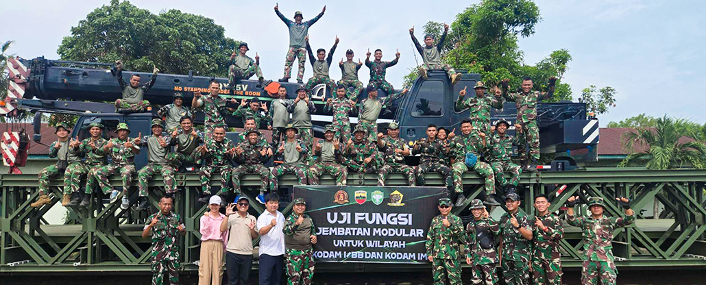
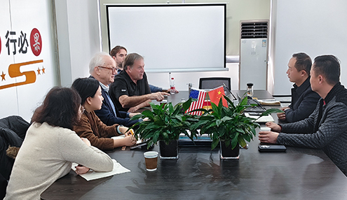
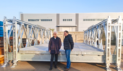
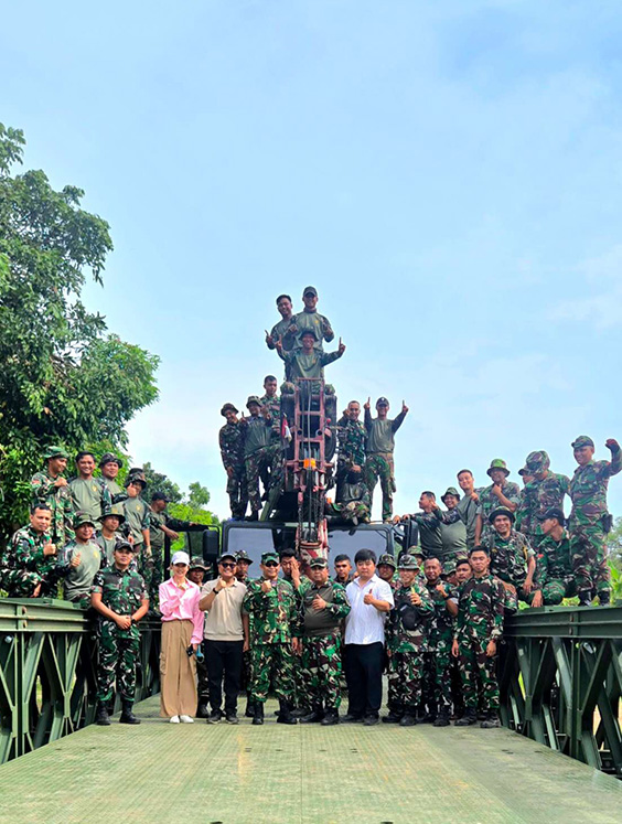
Póngase en contacto
Si tiene alguna pregunta sobre puentes de acero, no dude en contactarnos en cualquier momento

Ofrecemos soluciones confiables de puentes de acero a contratistas, gobiernos y empresas de ingeniería de todo el mundo.
-
2632407639@qq.com / sales@jhbaileybridge.com
-
+86-511-88881818
-
+86-17312965270
-
No. 19, Calle Xingye, ciudad de Shangdang, distrito de Dantu, ciudad de Zhenjiang, provincia de Jiangsu, China.
Derechos de autor © 2026 by Zhenjiang Jinhao Road & Bridge Supporting Engineering Co., Ltd. Todos los derechos reservados.
